Vacuum forming a laminate charge

a technology of laminate charge and vacuum, which is applied in the field of vacuum forming laminate charge to achieve the effect of increasing the consolidation of the laminate charge and reducing the risk of wrinkle formation

Active Publication Date: 2019-07-11
AIRBUS OPERATIONS LTD
View PDF0 Cites 2 Cited by
  • Summary
  • Abstract
  • Description
  • Claims
  • Application Information

AI Technical Summary

Benefits of technology

[0032]The forming surface may have any shape, including a relatively flat shape or a continuously curved shape with no corners. More typically the forming surface comprises a pair of faces; and a male or female corner positioned between the pair of faces. The pair of faces may be substantially planar, or they may be formed with ramps or other non-planar features. Optionally the first set of the vacuum openings are in one of the faces, and the second set of vacuum opening are in the other of the faces. Alternatively the first set of vacuum openings are in one of the faces and the second set of vacuum openings are in the male or female corner. In either case, the sequential application of vacuum can reduce the risk of wrinkles forming at the corner and / or increase consolidation of the laminate charge at the corner. Optionally a third set of the vacuum opening are in the other of the faces, and during a third stage of the sequence gas is sucked through the third set of the vacuum openings so that a third part of the laminate charge is pressed against the other of the faces. Gas is typically not sucked through the third set of vacuum openings during the first or second stage of the sequence.

Problems solved by technology

However, more typically the method further comprises stopping the injection of gas between the forming tool and the third part of the laminate charge, and generating a suction force between the forming tool and the impermeable sheet, which causes the impermeable sheet to press the third part of the laminate charge against the forming tool.

Method used


Image

  • Vacuum forming a laminate charge
  • Vacuum forming a laminate charge
  • Vacuum forming a laminate charge

Examples


Embodiment Construction

)

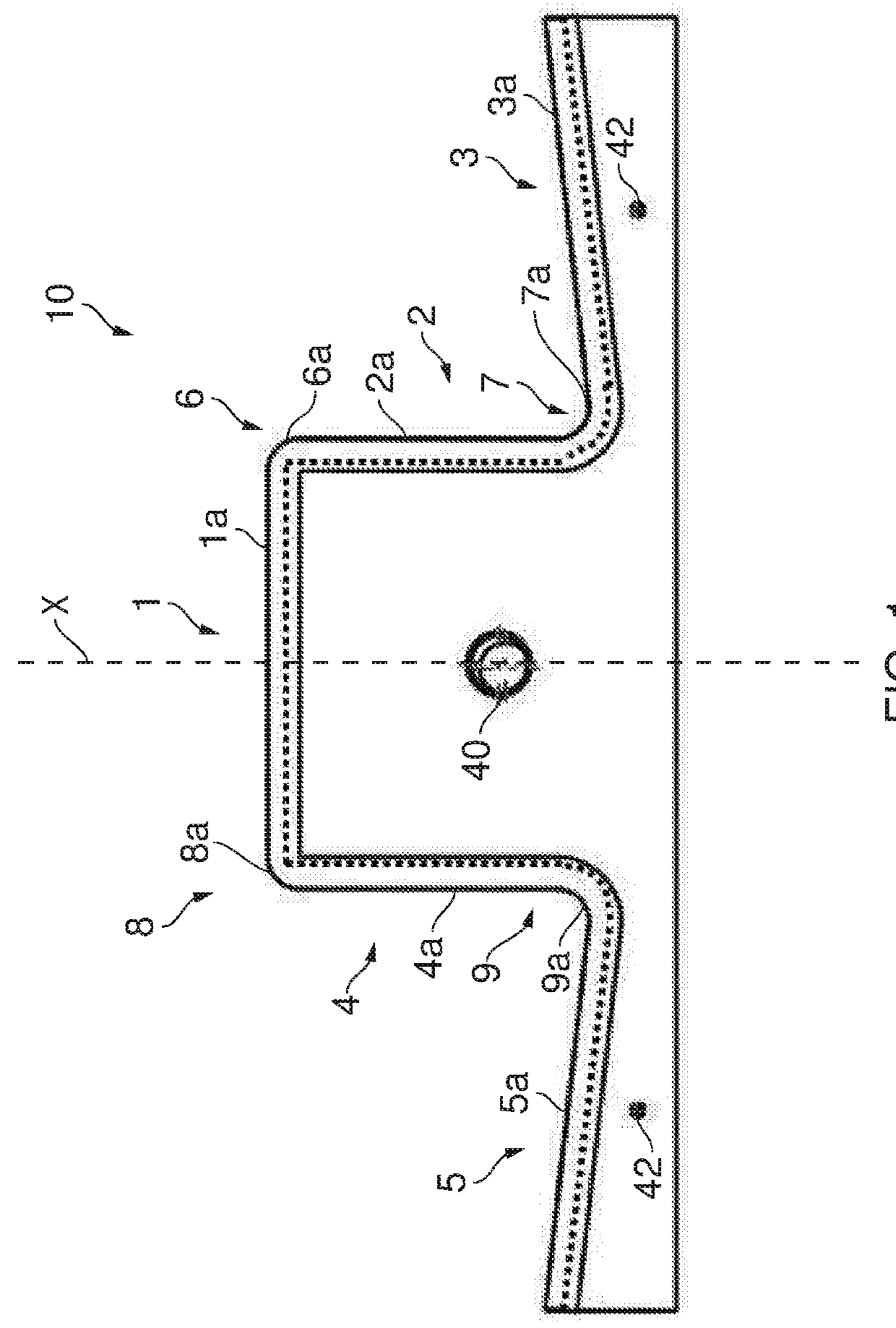
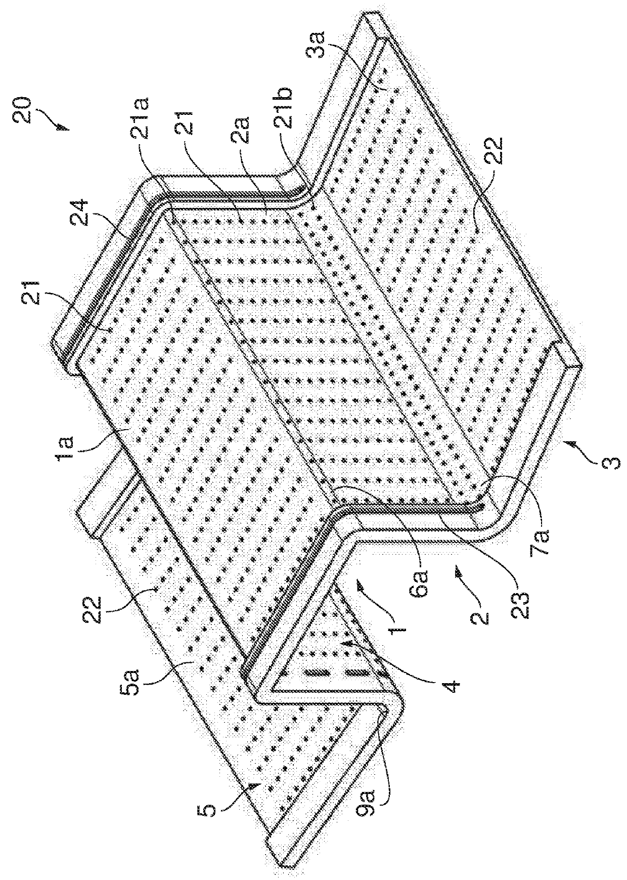
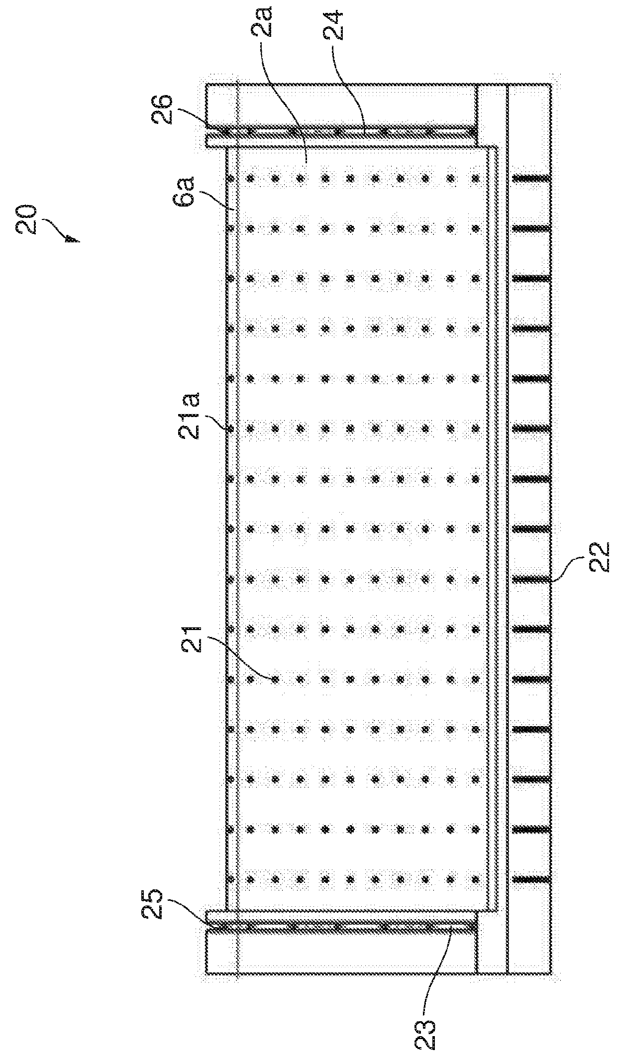
[0083]A forming tool 10 for forming a laminate charge is shown in FIG. 1. The forming tool comprises a forming part 20 shown in FIGS. 2-4, fitted onto a base 30 shown in FIGS. 5-7.

[0084]The forming part 20 has five parts 1-5 forming an “omega shape”. The five parts 1-5 are connected by curved corner parts 6-9. Each part 1-5 has a respective outer face 1a-5a which is approximately planar, and each corner part 6-9 has a curved outer face 6a-9a forming either a male corner or a female corner. Thus a first male corner 6a is positioned between the first and second faces 1a, 2a of the forming part; and a first female corner 7a is positioned between the second and third faces 2a, 3a of the forming part. The other half of the forming part 20 is a mirror image, as indicated by mirror plane X in FIG. 1, with a second male corner 8a positioned between the first and fourth faces 1a, 4a of the forming part; and a second female corner 9a positioned between the fourth and fifth faces 4a, 5a of th...


PUM

PropertyMeasurementUnit
suctionaaaaaaaaaa
chargeaaaaaaaaaa
suction forceaaaaaaaaaa

Abstract

A method of forming a laminate charge, and a forming tool and apparatus for forming a laminate charge is disclosed. In a forming step, a suction force is generated between a forming tool and an impermeable sheet which causes the impermeable sheet to press the laminate charge against a male corner of the forming tool and into a female corner of the forming tool. The male corner of the forming tool is positioned between first and second parts of the laminate charge, and the female corner of the forming tool is positioned between second and third parts of the laminate charge. During the forming step, gas is injected between the forming tool and part of the laminate charge to create a gas cushion between the forming tool and the third part of the laminate charge. This gas cushion inhibits the third part of the laminate charge from becoming clamped against the forming tool as the laminate charge is pressed into the female corner of the forming tool.

Description

FIELD OF THE INVENTION[0001]The present invention relates to a method of forming a laminate charge. The invention also relates to a forming tool and apparatus for forming a laminate charge. The charge is typically, although not exclusively, either a composite material or a preform which is subsequently infused to form a composite material.BACKGROUND OF THE INVENTION[0002]A known method of vacuum moulding a composite material is described in U.S. Pat. No. 4,562,033. Prepregs are placed on a heated former and covered with a sheet of a micro-porous film material, a breather material and an impermeable membrane.[0003]A problem with some known vacuum moulding processes is that it can be difficult for the charge to be easily sucked into the female corner of the forming tool without becoming clamped against the forming tool.[0004]Another known method for the shaping of a sheet of preform material is described in U.S. Pat. No. 4,946,640.SUMMARY OF THE INVENTION[0005]A first aspect of the in...

Claims


Application Information

Patent Timeline
Patent Type & Authority Applications(United States)
IPC IPC(8): B29C70/44B29B11/16
CPCB29C70/44B29B11/16B29C70/443B29C70/541B29D99/0003
Inventor WALLACE, ALEXANDER STEPHEN
Owner AIRBUS OPERATIONS LTD
Why Eureka
Try Eureka