
Shift device

a technology of shifting body and gear, which is applied in the direction of gearing control, gearing element, belt/chain/gearing, etc., can solve the problem of restricting the movement of the shift body

Active Publication Date: 2019-07-11
KK TOKAI RIKA DENKI SEISAKUSHO
View PDF5 Cites 2 Cited by
  • Summary
  • Abstract
  • Description
  • Claims
  • Application Information

AI Technical Summary

Benefits of technology

The invention offers a shift device that simplifies the mechanism for moving a restricting body, which is a component used in shifting gears in a vehicle transmission. By engaging a single engaged-with portion on the driving body with multiple restricting bodies, the movement of the shift body is restricted, and the mechanism can be made more simple. Additionally, the invention reduces stresses on the displaced portion and the restricting bodies during load input, which improves the overall performance of the shift device.

Problems solved by technology

As a result, movement of the shift body is restricted.

Method used


Image

  • Shift device
  • Shift device
  • Shift device

Examples


Embodiment Construction

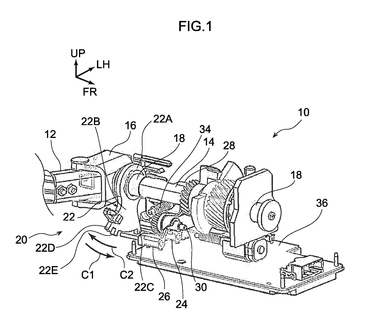
[0025]A shift lever device 10 that serves as a shift device relating to an exemplary embodiment is shown in FIG. 1 in a perspective view that is seen from the side opposite a shift lever 12. Note that, in the drawings, the frontward direction of the shift lever device 10 is indicated by arrow FR, the leftward direction of the shift lever device 10 is indicated by arrow LH, and the upward direction of the shift lever device 10 is indicated by arrow UP. Further, the forward, leftward and upward directions of the shift lever device 10 respectively coincide with the frontward, leftward and upward directions of a vehicle.

[0026]The shift lever device 10 relating to the present exemplary embodiment is a so-called column type device in which the shift lever 12 that serves as a shift body extends toward a lateral side of a steering column of the vehicle, and the shift lever device 10 is installed (set) at the steering column of the vehicle.

[0027]The shift lever device 10 has a main shaft 14 ...


PUM


Abstract

A shift lever device has a shift lever that is moved and whose shift position is changed, and a detent plate that is displaced due to the shift lever being moved. The shift lever device has a first lock bar and a second lock bar that can move toward the detent plate side or a side opposite from the detent plate, and, due to the first lock bar and the second lock bar engaging with portions of the detent plate, a range over which the detent plate is displaced is restricted, and a range of movement of the shift lever is restricted. The shift lever device has a cam that has a single engaged-with portion with which the first lock bar and the second lock bar engage, and, due to the cam being displaced, the first lock bar and the second lock bar are moved.

Description

CROSS-REFERENCE TO RELATED APPLICATION[0001]This application claims priority under 35 USC 119 from Japanese Patent Application No. 2018-000840 filed Jan. 5, 2018, the disclosure of which is incorporated by reference herein.BACKGROUNDField of Invention[0002]The present disclosure relates to a shift device.Related Art[0003]Japanese Patent Application Laid-Open (JP-A) No. 2017-114170 discloses a shift locking device having a knob that is changed to one shift position among plural shift positions by being operated by a vehicle occupant, and a shift locking mechanism that restricts operation of the knob. In the shift device disclosed in JP-A No. 2017-114170, operation of the knob is restricted by a restricting portion that structures a portion of the shift locking mechanism being engaged with a portion of a knob main body that rotates integrally with the knob.[0004]By the way, in a shift device in which the operating range of an operating portion such as a knob or the like is restricted ...

Claims


Application Information

Patent Timeline
Patent Type & Authority Applications(United States)
IPC IPC(8): F16H59/10F16H59/02F16H61/22F16H61/24
CPCF16H59/10F16H59/0278F16H61/22F16H61/24F16H2061/247F16H59/105
Inventor WATANABE, HIRONORIIMAI, KOJIMAKIMURA, MUNETOSHI
Owner KK TOKAI RIKA DENKI SEISAKUSHO
Learn More