Downhole tool string

Inactive Publication Date: 2019-07-18
QINTERRA TECH
View PDF6 Cites 0 Cited by
  • Summary
  • Abstract
  • Description
  • Claims
  • Application Information

AI Technical Summary

Benefits of technology

[0022]For the triggering of the severing step many different options are available. For instance, a timer can be set to go off after a certain amount of time or at a specific instant in time, wherein this time must be set to be enough to release the severing tool and bring the remainder of the downhole tool string (also referred to as the upper part of the downhole tool string) at a safe distance. Alternatively, an electrical or optical wire connection is maintained between said separated parts, such that the triggering can be done remotely by the remainder of the downhole tool string. In yet a further alternative embodiment a wireless connection is used between the remainder of the downhole tool string and the severing tool, or between the severing tool and the surface equipment.
[0023]It must also be stressed that step of triggering the pipe-severing tool to severe may include multiple sub-steps, wherein in a first sub-step the tubular structure is weakened or loosened and in a second sub-step the severing or cutting of the tubular structure is completed. For example first, in a first sub-step, the tubular structure is locally weakened at a respective joint that is nearest to the free point, for instance by means of an explosion, where after, in a second sub-step, the tubular structure is unscrewed at the same joint using the surface equipment. The invention is applicable as long as there is at least one sub-step, which is harmful or destructive to the downhole equipment. If the step of triggering comprises multiple sub-steps then it is important that the remainder of the downhole tool string is withdrawn at least before the sub-step that is harmful or destructive to th

Problems solved by technology

This results in costly downtime, ranging anywhere from several thousands of dollars up to several million

Method used


Image

  • Downhole tool string
  • Downhole tool string
  • Downhole tool string

Examples


Embodiment Construction

[0040]It should be noted that the above-mentioned and below-discussed embodiments illustrate rather than limit the invention, and that those skilled in the art will be able to design many alternative embodiments without departing from the scope of the appended claims. In the claims, any reference signs placed between parentheses shall not be construed as limiting the claim. Use of the verb “comprise” and its conjugations does not exclude the presence of elements or steps other than those stated in a claim. The article “a” or “an” preceding an element does not exclude the presence of a plurality of such elements. The mere fact that certain measures are recited in mutually different dependent claims does not indicate that a combination of these measures cannot be used to advantage.

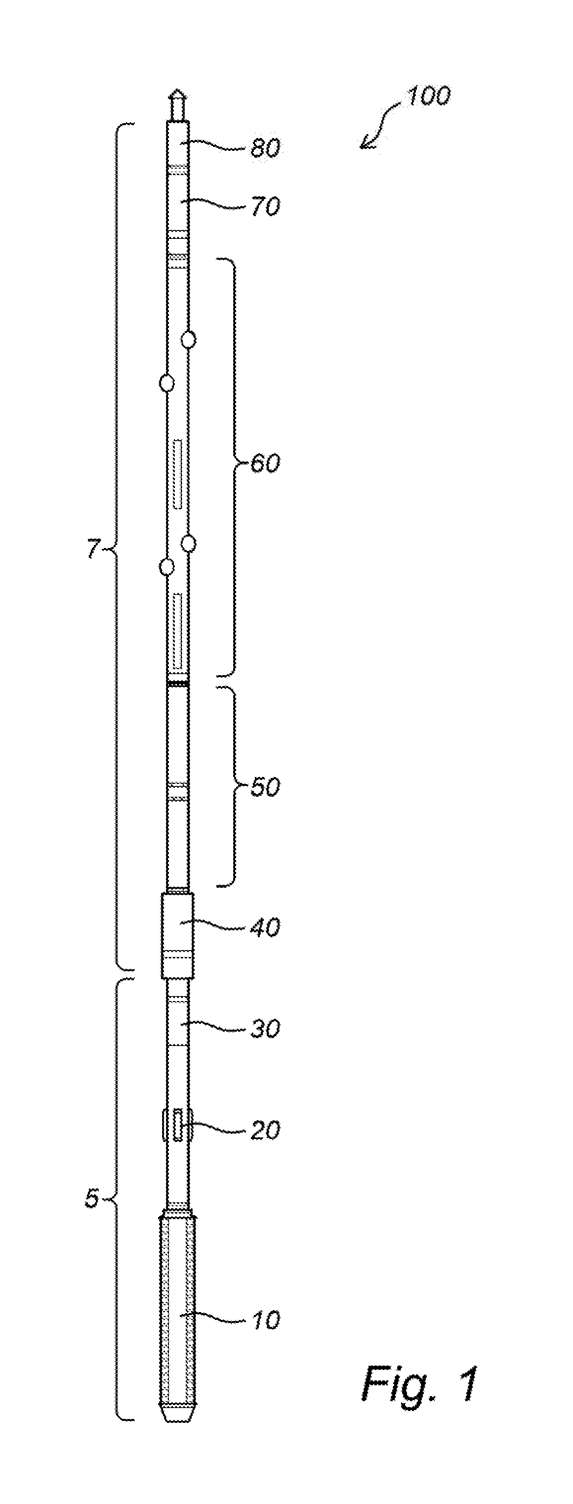
[0041]FIG. 1 shows an embodiment of the downhole tool string 100 in accordance with the invention. This embodiment uses a drill collar-severing tool, but the invention is not limited to such severing tool. T...


PUM


Abstract

The invention relates to a relates to a downhole tool string wherein the upper part of the string includes a release tool for releasably coupling with a pipe-severing tool.

Description

CROSS-REFERENCE TO RELATED APPLICATIONS[0001]This application is continuation of U.S. application Ser. No. 15 / 536,489 filed Jun. 15, 2017 which is the National Phase of PCT Application No. PCT / NO2015 / 050244 filed 15 Dec. 2015, which claims priority to Norwegian Patent Application No. 20141536 filed 19 Dec. 2014, each of which is incorporated herein by reference.STATEMENT REGARDING FEDERALLY SPONSORED RESEARCH[0002]Not applicableNAMES OF THE PARTIES TO A JOINT RESEARCH AGREEMENT[0003]Not applicableREFERENCE TO A SEQUENCE LISTING[0004]Not applicableBACKGROUND OF THE INVENTION[0005]The invention relates to a method for recovering a tubular structure from a well, and in particular to a method for recovering a stuck drill pipe from a well, particularly a highly deviated or horizontal well. The invention further relates to a downhole tool for use in such method.[0006]Pipe recovery operations are used in drilling operations in the oil and gas industry, where the drill string can become stu...

Claims


Application Information

Patent Timeline
IPC IPC(8): E21B29/00E21B29/02E21B23/01
CPCE21B29/002E21B29/02E21B23/01E21B2023/008E21B23/001
Inventor ARNALY, GEORGES EMILE
Owner QINTERRA TECH
Why Eureka
Try Eureka