Trigger switch

Active Publication Date: 2019-07-25
ORMON CORP
View PDF5 Cites 2 Cited by
  • Summary
  • Abstract
  • Description
  • Claims
  • Application Information

AI Technical Summary

Benefits of technology

The present invention provides a trigger switch that can improve its resistance to vibration. This is achieved by adding a layer of elastic material on the outside of the switch housing. This makes it more durable and reliable in environments that have a lot of movement and can cause damage to sensitive components.

Problems solved by technology

However, due to the recent increase in capacity and power of electric power tools, there have been more cases where such a switch mechanism cannot sufficiently prevent the occurrence of chattering.

Method used


Image

  • Trigger switch
  • Trigger switch
  • Trigger switch

Examples


Embodiment Construction

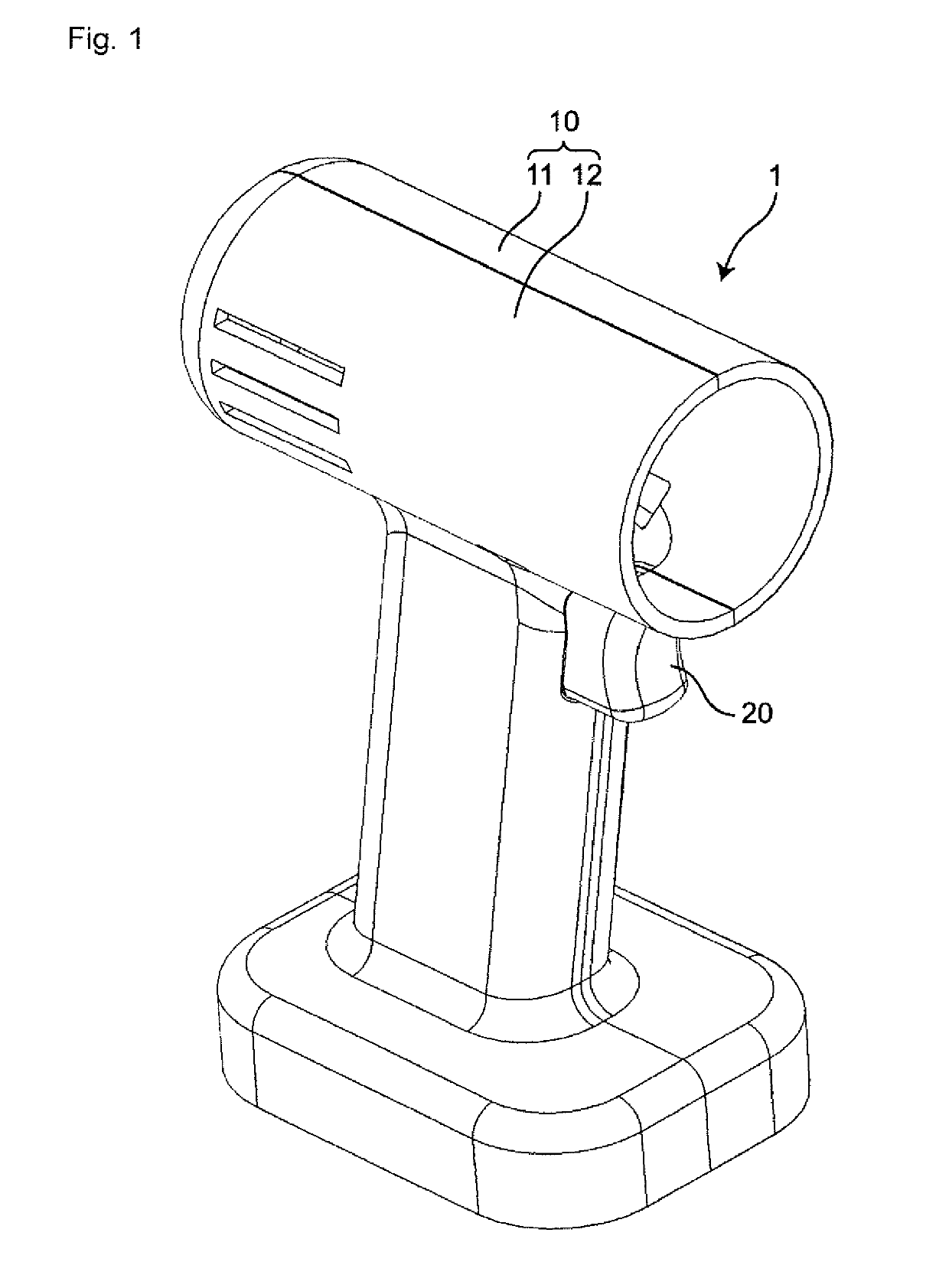
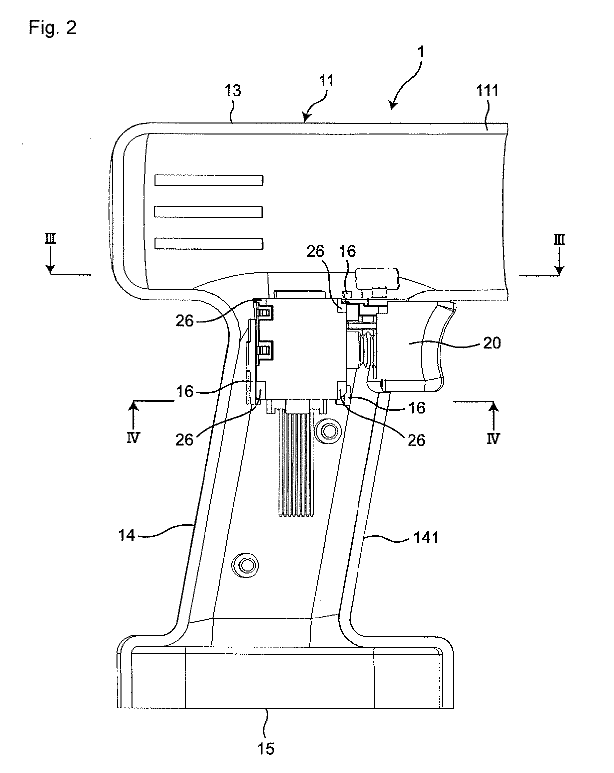
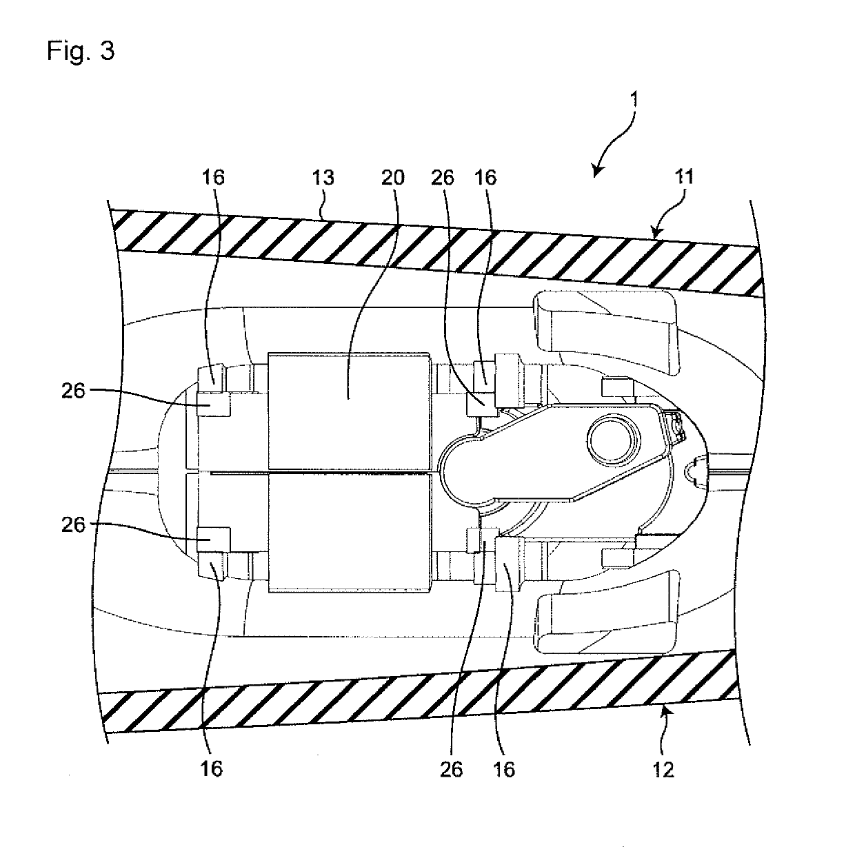
[0018]Hereinafter, embodiments of the present invention will be described with reference to the accompanying drawings. In the following description, terms (e.g., terms including “upper”, “lower”, “right”, “left”, “side”, and “end”) indicating specific directions or positions are used as necessary, but the use of these terms is for facilitating understanding of the invention with reference to the drawings, and the technical scope of the present invention is not limited by the meaning of these terms. The following description is merely exemplary in nature and is not intended to limit the present invention, its application, or its usage. Further, the drawings are schematic, and ratios of dimensions and the like do not necessarily agree with actual ones. In embodiments of the invention, numerous specific details are set forth in order to provide a more thorough understanding of the invention. However, it will be apparent to one of ordinary skill in the art that the invention may be prac...


PUM


Abstract

A trigger switch has a switch housing fixed inside a tool housing of an electric power tool and internally having a holder, an operation unit provided outside the switch housing and connected to the switch housing so as to be approachable to and separable from the switch housing, a fixed contact provided in the holder, and a movable contact provided so as to face the fixed contact in the holder and configured to come into contact with and separate from the fixed contact in conjunction with an approaching motion and a separating motion of the operation unit with respect to the switch housing. A vibration damping elastic body is provided integrally on an outer surface of the switch housing.

Description

BACKGROUNDTechnical Field[0001]The present invention relates to a trigger switch used in an electric power tool.Related Art[0002]The trigger switch disclosed in Patent Document 1 includes a first housing and a second housing in which a switch mechanism is incorporated, and an operation unit that can be operated by a user with a finger and transmits an operational motion to the switch mechanism.[0003]Patent Document 1: Japanese Unexamined Patent Publication No. 2010-192452SUMMARY OF THE INVENTION[0004]In the trigger switch, a switch mechanism is used to improve vibration resistance, the switch mechanism having a structure in which two movable contacts are simultaneously press-fit to two fixed contacts while resisting the urging force of springs. However, due to the recent increase in capacity and power of electric power tools, there have been more cases where such a switch mechanism cannot sufficiently prevent the occurrence of chattering.[0005]One or more embodiments of the present ...

Claims


Application Information

Patent Timeline
IPC IPC(8): H01H13/04H01H13/60H01H9/02B25F5/00B25F5/02
CPCH01H13/04H01H13/60H01H9/02B25F5/006B25F5/02B25F5/00H01H71/12H01H9/102
Inventor KOYAMA, TAIKIMORII, MAKITOOMORI, KOJI
Owner ORMON CORP
Why Eureka
Try Eureka