Liquid crystal display device and liquid crystal production method

Inactive Publication Date: 2004-06-24
HITACHT MAXELL LTD
View PDF8 Cites 13 Cited by
  • Summary
  • Abstract
  • Description
  • Claims
  • Application Information

AI Technical Summary

Benefits of technology

0101] As shown in FIG. 29(b), it is possible to form a polymer dispersed liquid crystal film 2905 of polyester or urethane/liquid crystal on the top of the substrate 2801, the polymer dispersed liquid crystal film 2901 of PMMA/liquid crystal on the top of the liquid crystal film 2905, and then the polymer dispersed liquid crystal film 2903 of elastomer or acryl epoxy/liquid crystal on the top of the liquid crystal film 2901, thus producing the laminated polymer dispersed liquid crystal layer 2807 having durability against ultraviolet irradiation (UV) and resistance to thermal shock. If only the resistance to thermal shock is required, the liquid crystal film 2903 may be omitted. The polymer constituting the polymer dispersed liquid crystal film for the purpose of improving the resistance to thermal shock may be amorphous polyolefin, polyetherimide, polyamide, polycarbonate, polysulfone, polyethersulfone or polyetherketone.
0102] Mo

Problems solved by technology

However, various problems still remain in this type of display devices.
For example, (1) the thermal conductivity of the polymer is low, and then response speed is insufficient, (2) contrast is not uniform because temperature distribution over the device is not even, and (3) in case of matrix-addressing display, image becomes dim because of unclear pixell outline.
These problems are probably caused by the poor thermal response characteristic of this device since it includes polymer having low thermal conductivity.
Further, (4) the polymer is gradually deformed due to the affection of the repetitive thermal cycles, reducing the practical devi

Method used


Image

  • Liquid crystal display device and liquid crystal production method
  • Liquid crystal display device and liquid crystal production method
  • Liquid crystal display device and liquid crystal production method

Examples


embodiment 1

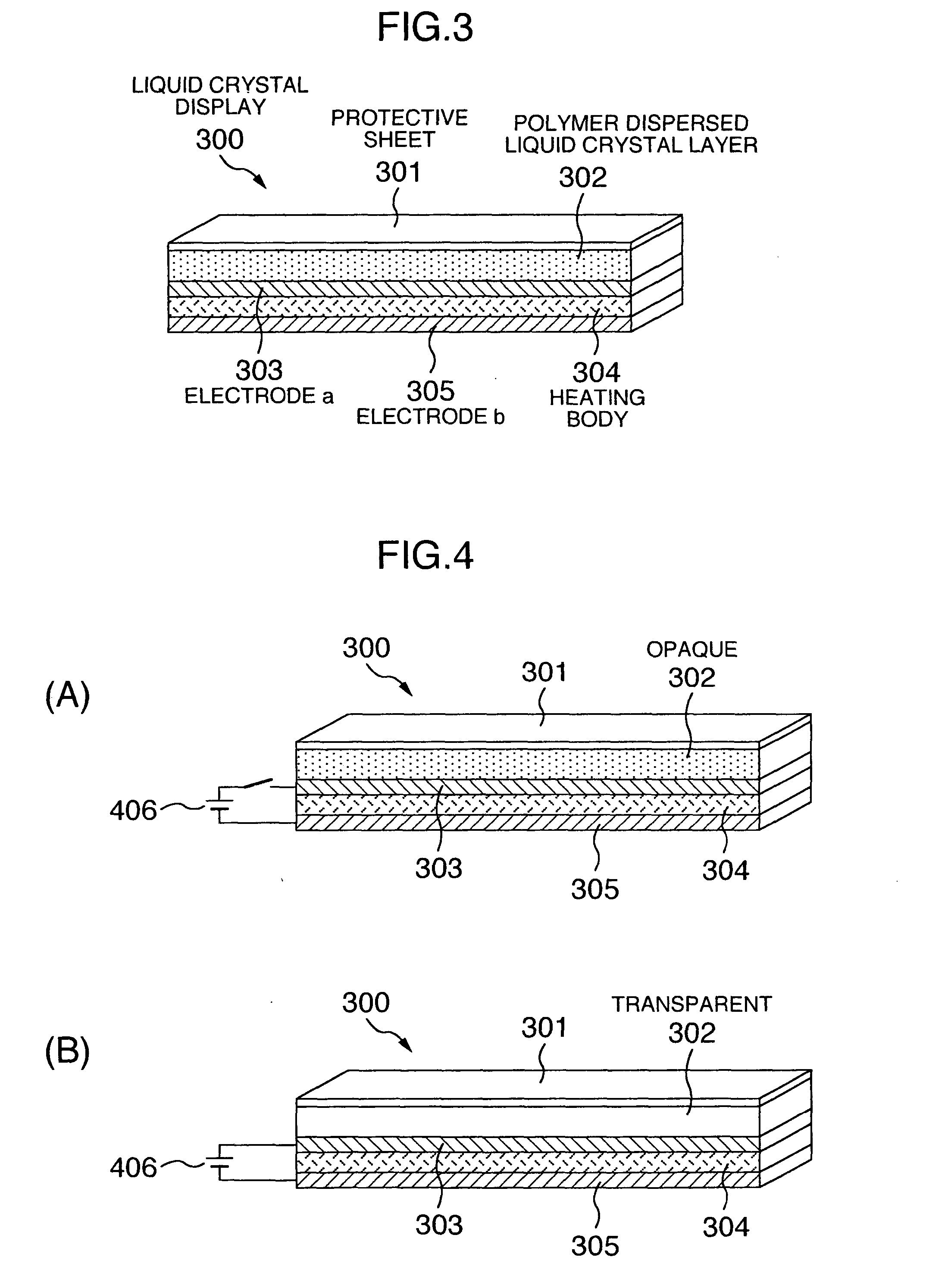
[0108] To produce the liquid crystal display 300 of the structure of FIG. 3, polyvinyl butyral (T.sub.g=50.degree. C.) was used as the polymer, and nematic liquid crystal (T.sub.NI=72.degree. C., .DELTA.n=0.246) as the liquid crystal. The weight ratio of the polymer and liquid crystal was 1:1. Then, the same conditions and operations as in the embodiment 1 were used and performed to produce a liquid crystal cell C.

embodiment 3

[0115] Embodiment 3

[0116] The following materials were mixed and well stirred with a homogenizer at room temperature for 15 minutes to produce a polymer dispersed liquid crystal composition solution.

[0117] Polymer: polymethyl methacrylate . . . 5 weight part

[0118] Liquid crystal: cyanobiphenyl-based E-8

[0119] made by B.D.H. Corp . . . 5 weight part

[0120] Solvent: acetone . . . 90 weight part

[0121] This mixture solution was coated on a PET film by an applicator to form a polymer dispersed liquid crystal film 15 .mu.m thick. The thickness of the liquid crystal layer was increased by superimposing liquid crystal films according to the lamination method of the invention. The lamination of liquid crystal films was made by compression bonding at 80.degree. C. for one minute on the apparatus, TOLAMI-DX-350 that came onto the market from Tokyo Laminex Corp. Various different samples were prepared by changing the number of laminated liquid crystal films, and the transmission factors of those...


PUM

PropertyMeasurementUnit
Fractionaaaaaaaaaa
Fractionaaaaaaaaaa
Fractionaaaaaaaaaa

Abstract

A thermal-responsive liquid crystal display having a polymer dispersed liquid crystal layer formed to have excellent response speed, good display characteristics, uniform thickness distribution, high thickness, high contrast and excellent resistance to thermal cycle. A polymer dispersed liquid crystal layer formed of a composition of a polymer and a liquid crystal is provided on a heating unit. The polymer is a thermoplastic resin, and the glass transition temperature (Tg) of the resin and the phase transition temperature (TNI) of the liquid crystal satisfy the condition of -20<=(Tg-TNI)<=20 (° C.). The polymer dispersed liquid crystal layer is formed by laminating a plurality of polymer dispersed liquid crystal films.

Description

[0001] The present invention generally relates to liquid crystal displays, and particularly to a liquid crystal display formed of a polymer dispersed liquid crystal layer having thermooptic effect or thermal response characteristic that includes a liquid crystal material, and a heating unit for driving this polymer dispersed liquid crystal layer.PRIOR ART[0002] Liquid crystal materials of which the optical characteristics are changed by temperature change have so far been used for the display of images. The liquid crystal materials for the display include smectic liquid crystal, nematic liquid crystal and cholesteric liquid crystal. It is known that these liquid crystal materials become transparent or opaque (clouded) or cause change of color when the molecular orientation of liquid crystal is changed by temperature change.[0003] On the other hand, display devices using polymer dispersed liquid crystal have been developed. This type of devices have excellent characteristics such as ...

Claims


Application Information

Patent Timeline
IPC IPC(8): G02F1/133G02F1/1334
CPCG02F1/1334G02F1/132
Inventor OOAE, KOUJIFUKAO, RYUZOYAMASHITA, YUJI
Owner HITACHT MAXELL LTD
Why Eureka
Try Eureka