Eureka AIR delivers breakthrough ideas for toughest innovation challenges, trusted by R&D personnel around the world.

Electrical connector with a latch structure

Active Publication Date: 2019-07-25
F TIME TECH INDAL
View PDF0 Cites 1 Cited by
  • Summary
  • Abstract
  • Description
  • Claims
  • Application Information

AI Technical Summary

Benefits of technology

The present invention is a type of electrical connector with latches that hold down the conductive components, making them easier to position. This invention improves the stability of the electrical connection.

Problems solved by technology

However, the demand for technology continues to increase, and the demand for electronic signal transmission is constantly changing.
However, in the aforesaid prior art electrical connector design, the conductive component 101 can be forced to deviate when a series connection is performed, thereby affecting signal stability and signal fluency.

Method used


Image

  • Electrical connector with a latch structure
  • Electrical connector with a latch structure
  • Electrical connector with a latch structure

Examples


Embodiment Construction

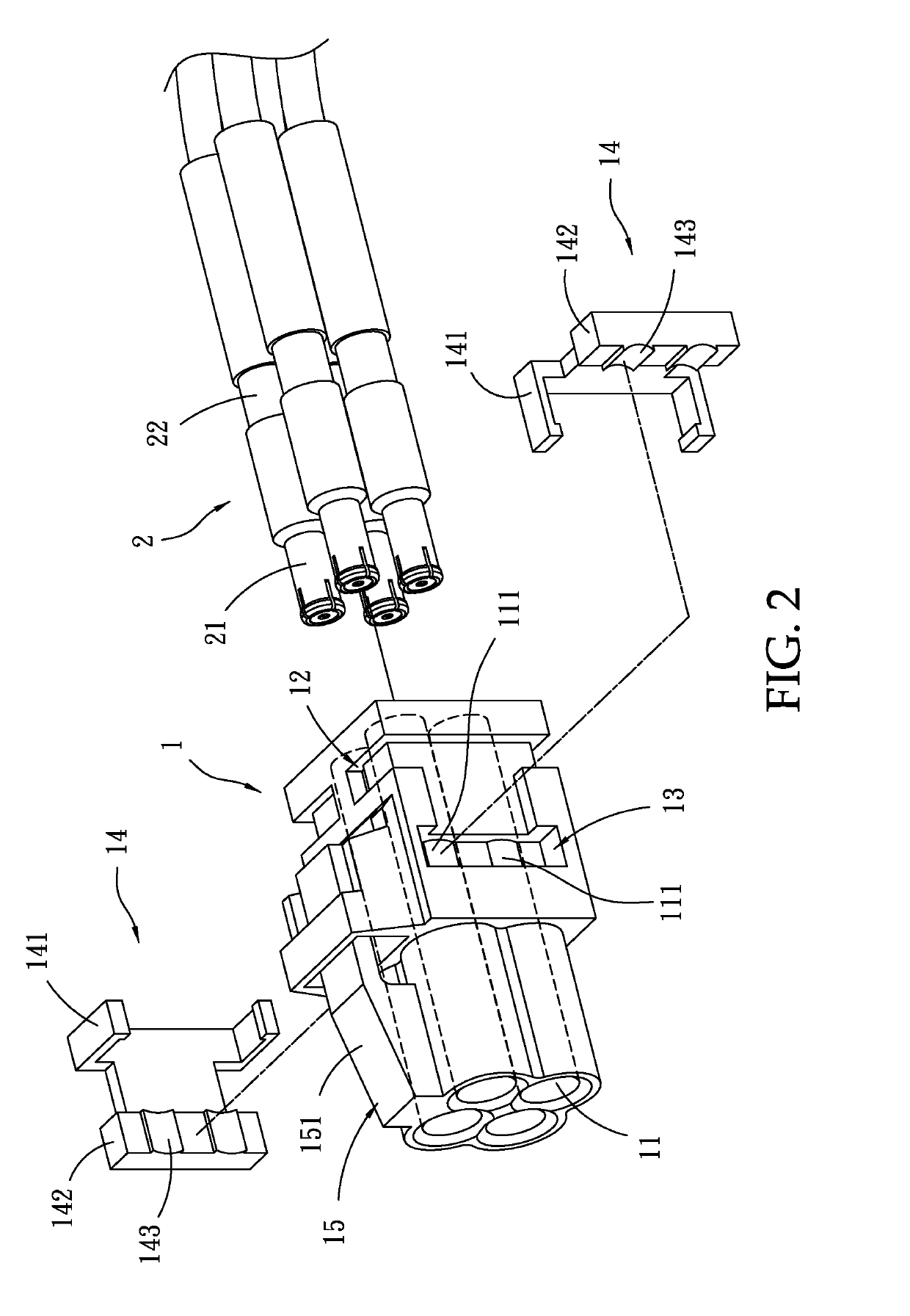
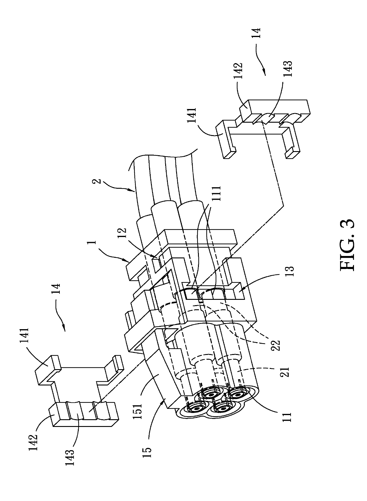
[0013]Referring to FIG. 2, an electrical connector in accordance with the present invention is shown. The electrical connector comprises a housing 1, and at least one conductive component 2. The housing 1 has at least one insertion slot 11 extending through opposing front and rear sides thereof. In this embodiment, the housing 1 is a multi-core electrical connector housing having a plurality of insertion slots 11. These insertion slots 11 have a circular cross section. The housing 1 further has an engagement groove 12 located on each of two opposing lateral sides thereof and extended to opposing top and bottom sides thereof, a locating groove 13 located on each of the two opposite lateral sides, and at least one, for example, two openings 111 located in each locating groove 13 in communication with one respective insertion slot 11.

[0014]Referring to FIG. 2 again, the electrical connector further comprises a plurality of, for example, two latches 14 respectively attached to the two o...


PUM


Abstract

An electrical connector includes a housing having insertion slots extended through opposing front and rear sides thereof, an engagement groove and a locating groove located on each of two opposite lateral sides thereof and an opening located in each locating groove in communication with one respective insertion slot, a plurality of conductive components respectively inserted into the insertion slots, each conductive component having a locating groove extended around the periphery thereof, and two latches each having a ring hook hooked in one respective engagement groove, a latch plate engaged into respective locating groove and a curved engagement surface located on the latch plate and inserted into one respective opening to engage the locating groove of one respective conductive component.

Description

BACKGROUND OF THE INVENTION1. Field of the Invention[0001]The present invention relates to electrical connector technology and more particularly, to an electrical connector with a latch structure that uses latches to hold down the conductive components.2. Description of the Related Art[0002]With the continuous updating of technology, various new electronic products have been introduced. Many electronic products are connected to other electronic devices by cables with the use of mating male and female connectors to achieve signal transmission.[0003]FIG. 1 illustrates an electrical connector according to the prior art. According to this design, the electrical connector comprises a housing 100, and a conductive component 101 mounted in the housing 100 for the connection of a mating connector. According to this design, the conductive component 101 is directly inserted into the housing 100 and secured in the housing 100 by an internal structure of the housing 100.[0004]However, the deman...

Claims


Application Information

Patent Timeline
IPC IPC(8): H01R13/426
CPCH01R13/426H01R2107/00H01R13/4361
Inventor PENG, CHANG-LINLIU, XIN-FUHUANG, YEN-HUATUNG, CHIH-HSUAN
Owner F TIME TECH INDAL
Why Eureka
Eureka Blog
Learn More