Electrical plug connector, electrical socket connector, electrical plug and socket connector assembly

a technology of electrical plugs and sockets, applied in the direction of electrical apparatus, securing/insulating coupling contact members, coupling device connections, etc., can solve problems such as temperature rise, and achieve the effects of high structural stability, convenient installation, and high positioning stability

Active Publication Date: 2014-03-04
ACES ELECTRONICS CO LTD
View PDF35 Cites 20 Cited by
  • Summary
  • Abstract
  • Description
  • Claims
  • Application Information

AI Technical Summary

Benefits of technology

[0007]The present invention has been accomplished under the circumstances in view. It is therefore the main object of the present invention to provide an electrical plug and socket connector assembly, which facilitates installation and has high structural stability.
[0008]To achieve this and other objects of the present invention, an electrical plug and socket connector assembly comprises an electrical plug connector and an electrical socket connector. The electrical plug connector and the electrical socket connector each comprise an electrically insulative housing and a plurality of conducting terminals mounted in the electrically insulative housing. The electrically insulative housing comprises a plurality of insertion slots and terminal holes for receiving the conducting terminals, and a plurality of springy hooks suspending in top and bottom sides in the insertion slots. Each conducting terminal of each of the electrical plug connector and electrical socket connector comprises two side panels spaced by a gap, multiple fins extended from top and bottom edges of the side panels and suspending in top and bottom sides of the gap and hooked in the insertion slots by the springy hooks, and two contact end portions respectively forwardly extended from respective opposite ends of the two side panels. Further, each springy hook comprises a bevel face located on a distal end thereof remote from the associating terminal hole, a vertical stop edge disposed at a back side of the bevel face and a stepped rear stop portion disposed adjacent to the associating terminal hole. When inserting the conducting terminals into the respective insertion slots in the electrically insulative housing, the fins will be moved over the respective bevel faces of the springy hook into the space between the vertical stop edges and stepped rear stop portions of the respective springy hooks and then positively stopped between the vertical stop edges and stepped rear stop portions of the respective springy hooks, prohibiting the respective conducting terminals from forward and backward displacement relative to the electrically insulative housing. Thus, the electrical plug connector and the electrical socket connector have the characteristics of ease of installation and high positioning stability.
[0009]Further, the fins of the conducting terminals, except the function for engagement with the springy hooks, increase the heat radiation surface area of the conducting terminals.

Problems solved by technology

With respect to power supply, conducting a high-current power supply through a power circuit will increase the impedance, causing a rise in temperature.

Method used


Image

  • Electrical plug connector, electrical socket connector, electrical plug and socket connector assembly
  • Electrical plug connector, electrical socket connector, electrical plug and socket connector assembly
  • Electrical plug connector, electrical socket connector, electrical plug and socket connector assembly

Examples


Embodiment Construction

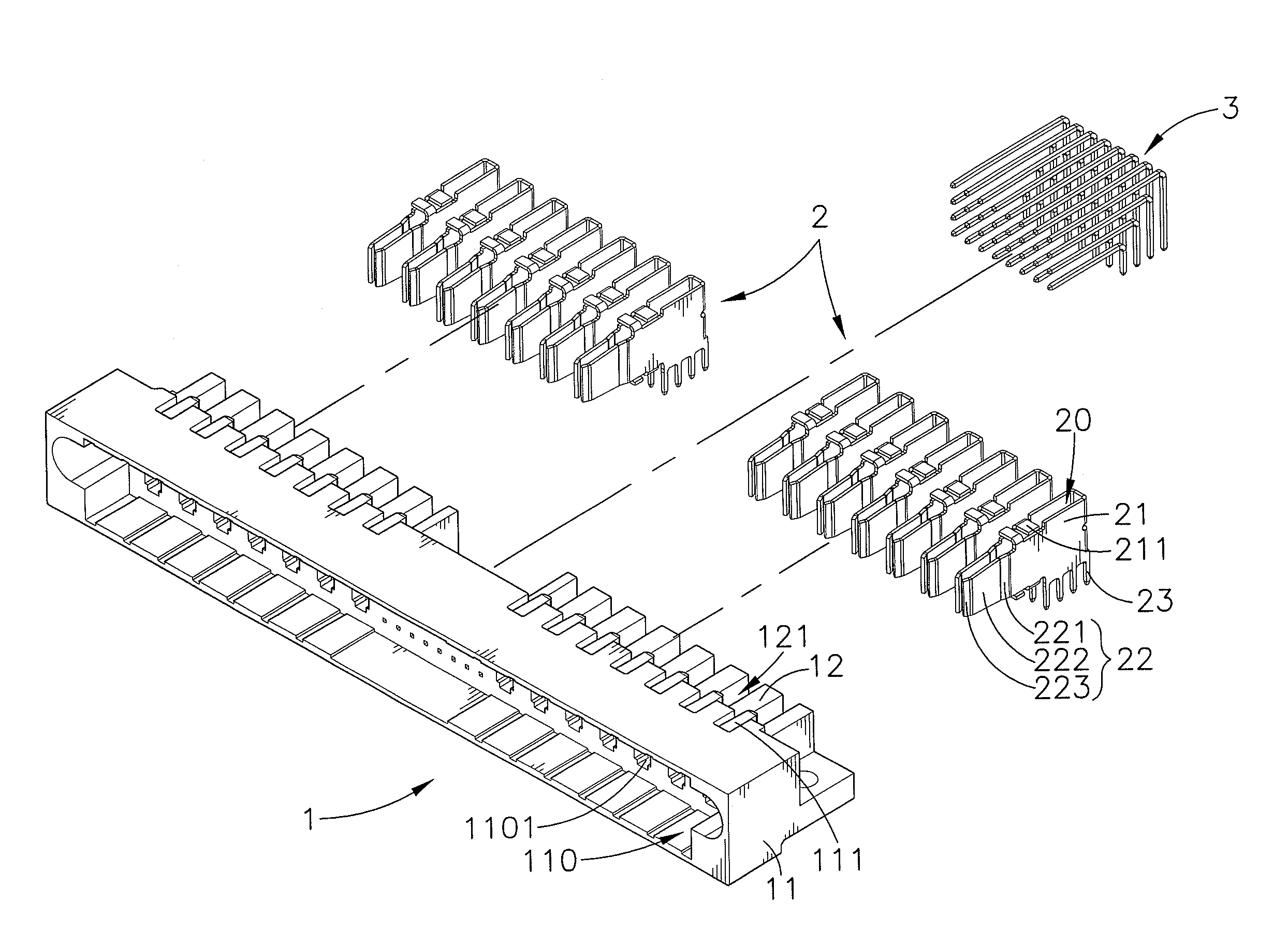
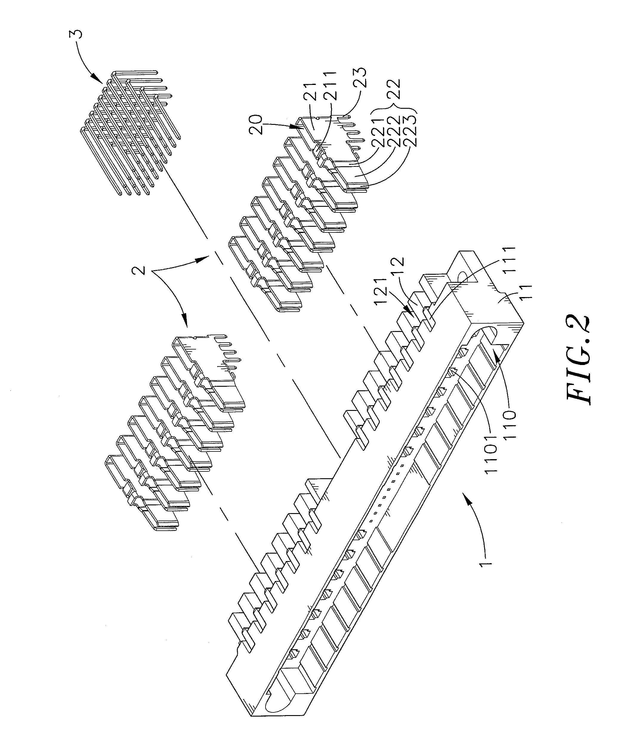
[0024]Referring to FIGS. 1, 2 and 3, an electrical plug connector in accordance with the present invention is shown comprising an electrically insulative housing 1, and a plurality of conducting terminals 2.

[0025]The electrically insulative housing 1 comprises a mating portion 11, a receiving chamber 110 defined in one side of the mating portion 11, a plurality of partition plates 12 arranged in two sets at an opposite side of the mating portion 11, a plurality of insertion slots 121 respectively defined between each two adjacent partition plates 12 of each of the two sets of partition plates 12, a plurality of terminal holes 1101 formed in the mating portion 11 and respectively disposed in communication between the insertion slots 121 and the receiving chamber 110, and a plurality of springy hooks 111 extended from the mating portion 11 and respectively suspending in top and bottom sides in each of the insertion slots 12. Further, the terminal holes 1101 have a relatively shorter h...


PUM


Abstract

An electrical plug and socket connector assembly includes an electrical plug connector and an electrical socket connector each including an electrically insulative housing and conducting terminals inserted into respective insertion slots in the electrically insulative housing, the electrically insulative housing having springy hooks suspending in top and bottom sides in each insertion slot, each conducting terminal of each of the electrical plug connector and electrical socket connector defines two side panels spaced by a gap, multiple fins extended from top and bottom edges of the side panels and suspending in top and bottom sides of the gap and hooked in the insertion slots by the springy hooks, and two contact end portions respectively forwardly extended from respective opposite ends of the two side panels.

Description

[0001]This application claims the priority benefit of Taiwan patent application number 100216036, filed on Aug. 26, 2011.BACKGROUND OF THE INVENTION[0002]1. Field of the Invention[0003]The present invention relates to electrical connector technology and more particularly, to an electrical plug and socket connector assembly, which, subject to its smart structural design, facilitates installation and has high structural stability.[0004]2. Description of the Related Art[0005]When designing an electrical connector for joining electrical circuits, a designer will pay attention to the two basic parts, i.e., signal and power supply. When designing a signal circuit, a designer normally will not consider the factor of current variation for the reason that the applied current is normally low. However, with respect to the transmission of signals, a designer usually will consider the nature of the carrier (high frequency, low frequency) and many other factors (static interference, magnetic inte...

Claims


Application Information

Patent Timeline
Patent Type & Authority Patents(United States)
IPC IPC(8): H01R13/40
CPCH01R13/627H01R12/58H01R12/724
Inventor WU, KUN-SHEN
Owner ACES ELECTRONICS CO LTD
Why Eureka
Try Eureka