Extreme ultra violet light source apparatus

a light source and ultra violet technology, applied in the field of extreme ultra violet (euv) light source apparatus, can solve the problems of unstable position, varying intensity of radiated euv light, and loss of stability of droplet positions

Active Publication Date: 2009-09-03
GIGAPHOTON
View PDF17 Cites 21 Cited by
  • Summary
  • Abstract
  • Description
  • Claims
  • Application Information

AI Technical Summary

Benefits of technology

[0017]According to the present invention, since there is provided the charging electrode for charging the droplets when the target material in the jet form injected from the injection nozzle is broken u

Problems solved by technology

However, in the conventional technology, the stability of the positions of droplets are gradually lost and the positions become unstable before the droplets reach the laser application point, and variations in positions are increased especially in the traveling direction of the droplets.
As a result, the laser beam is no longer applied to the droplets constantly in the same condition, and there is a problem that the intensity of the radiated EUV light varies and, in the worst case, the laser beam is not applied to the droplets and no EUV light is generated.
However, since the laser poser to be used in the EU

Method used


Image

  • Extreme ultra violet light source apparatus
  • Extreme ultra violet light source apparatus
  • Extreme ultra violet light source apparatus

Examples


first embodiment

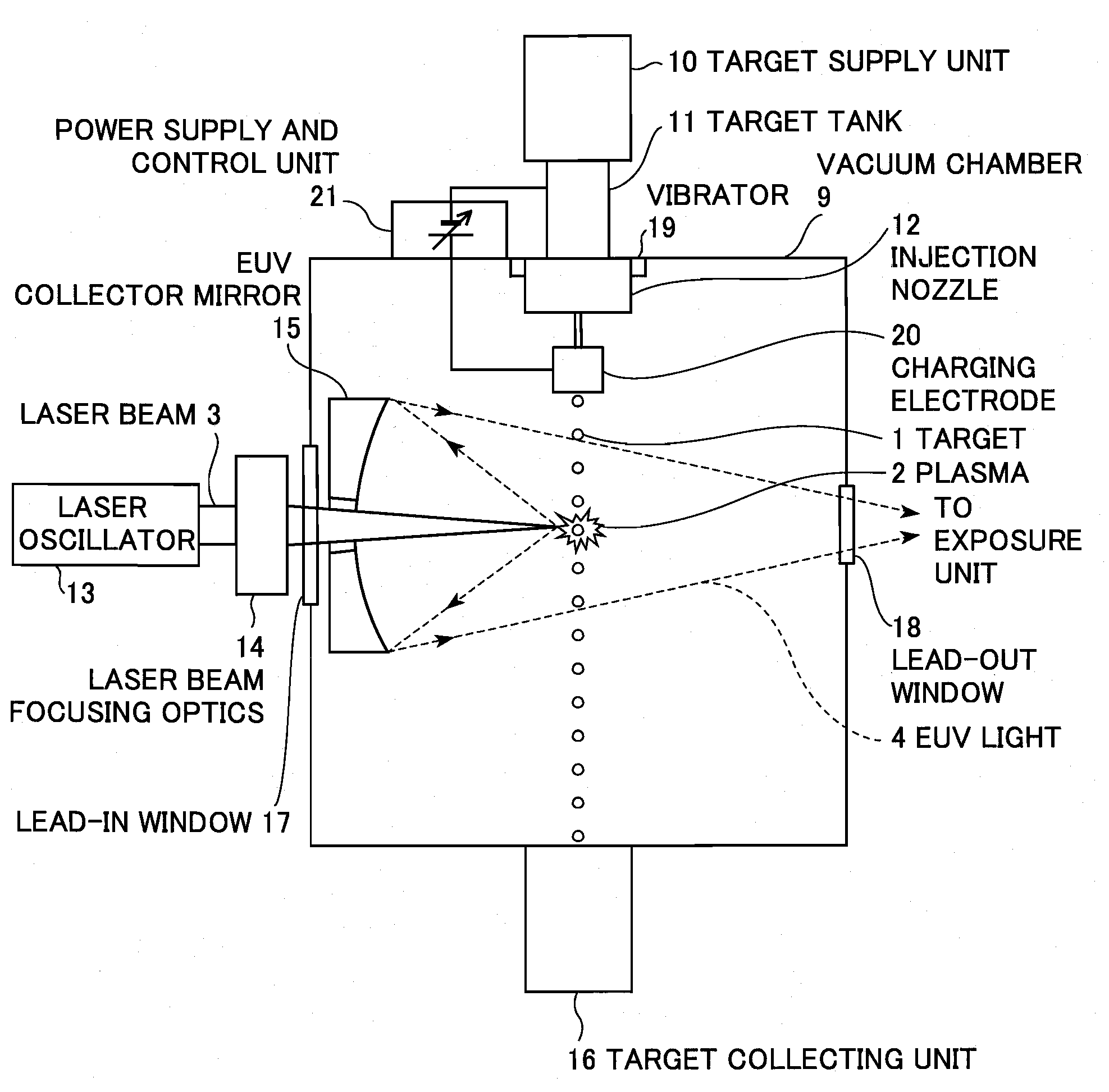
[0027]FIG. 1 is a schematic diagram showing an extreme ultra violet (EUV) light source apparatus according to the present invention. The EUV light source apparatus adopts an LPP (laser produced plasma) type and used as a light source of exposure equipment.

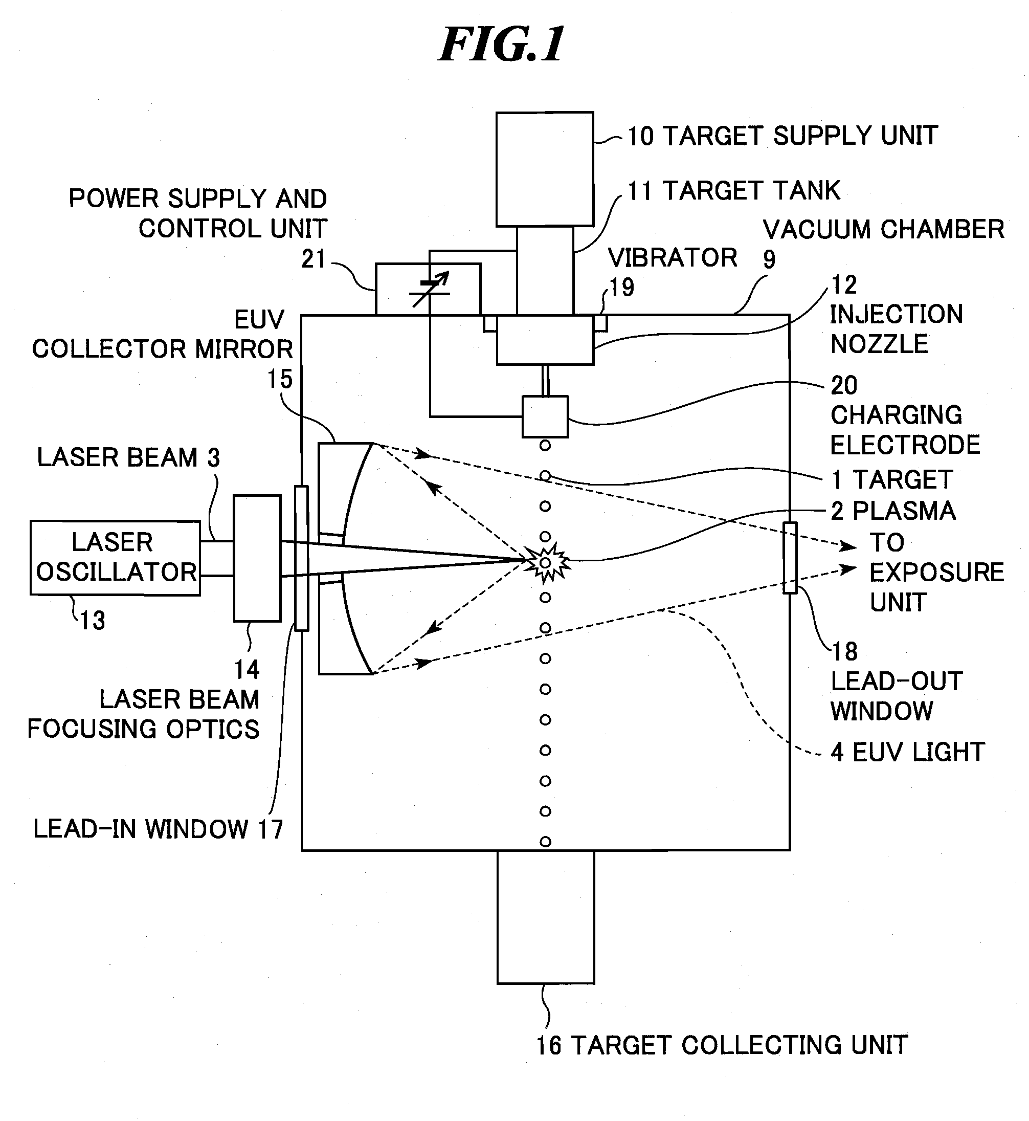
[0028]As shown in FIG. 1, the EUV light source apparatus according to the embodiment includes a vacuum chamber (EUV light generation chamber) 9 in which EUV light is generated, a target supply unit 10 that supplies a target material, a target tank 11 for storing the target material therein, an injection nozzle (nozzle unit) 12 for injecting the target material in a jet form, a laser oscillator 13, a laser beam focusing optics 14, an EUV collector mirror 15, a target collecting unit 16, a vibration mechanism 19, a charging electrode 20, a power supply and control unit 21. Here, the target supply unit 10 to the injection nozzle 12 form a target supply division for supplying the target material into the vacuum chamber 9.

[0029]The vacu...

second embodiment

[0047]Next, the present invention will be explained.

[0048]FIG. 6 shows a droplet target generating device and a part around the device in an EUV light source apparatus according to the second embodiment of the present invention. In the second embodiment, at least a part of an injection nozzle 12a has an electric insulation property. The rest is the same as that of the first embodiment.

[0049]Generally, the actual length of the jet part ejected from the injection nozzle is extremely short. For example, the length of the jet part is 1 mm or less in most cases when vibration is applied by a vibrator to the jet ejected from an injection nozzle having an inner diameter of 15 um at a velocity of 20 m / s and droplets are formed. Therefore, from a practical point of view, in order to allow the droplet generation position to exist within the injection nozzle in an ideal condition as explained in the first embodiment, it is necessary to place the charging electrode as close to the injection noz...


PUM


Abstract

In an LPP type EUV light source apparatus, the intensity of radiated EUV light is stabilized by improving the positional stability of droplets. The extreme ultra violet light source apparatus includes: a chamber in which extreme ultra violet light is generated; a target supply division including a target tank for storing a target material therein and an injection nozzle for injecting the target material in a jet form, for supplying the target material into the chamber; a charging electrode applied with a direct-current voltage between the target tank and itself, for charging droplets when the target material in the jet form injected from the injection nozzle is broken up into the droplets; a laser for applying a laser beam to the droplets of the target material to generate plasma; and a collector mirror for collecting extreme ultra violet light radiated from the plasma to output the extreme ultra violet light.

Description

BACKGROUND OF THE INVENTION[0001]1. Field of the Invention[0002]The present invention relates to an extreme ultra violet (EUV) light source apparatus to be used as a light source of exposure equipment.[0003]2. Description of a Related Art[0004]Recent years, as semiconductor processes become finer, photolithography has been making rapid progress to finer fabrication. In the next generation, microfabrication of 100 nm to 70 nm, further, microfabrication of 50 nm or less will be required. Accordingly, in order to fulfill the requirement for microfabrication of 50 nm or less, for example, the development of exposure equipment is expected by combining an EUV light source generating EUV light having a wavelength of about 13 nm and a reduced projection reflective optics.[0005]As the EUV light source, there are three kinds of light sources, which include an LPP (laser produced plasma) light source using plasma generated by applying a laser beam to a target (hereinafter, also referred to as ...

Claims


Application Information

Patent Timeline
IPC IPC(8): G01J3/10
CPCH05G2/003H05G2/006H05G2/008
Inventor NAKANO, MASAKIENDO, AKIRA
Owner GIGAPHOTON
Why Eureka
Try Eureka