Display device and mounting structure of vehicle meter

Inactive Publication Date: 2019-08-01
HONDA MOTOR CO LTD
View PDF3 Cites 0 Cited by
  • Summary
  • Abstract
  • Description
  • Claims
  • Application Information

AI Technical Summary

Benefits of technology

[0021]According to the aspect of (9), it is possible to make the light detector hard for the user to see, and it is possible to im

Problems solved by technology

For example, in the case in which the amount of external light is large, for example, a case in which direct sunlight is incident, it is difficult to see an image when luminance of the display device is low.
In the technique described in Patent Document 1, it was im

Method used


Image

  • Display device and mounting structure of vehicle meter
  • Display device and mounting structure of vehicle meter
  • Display device and mounting structure of vehicle meter

Examples


embodiment

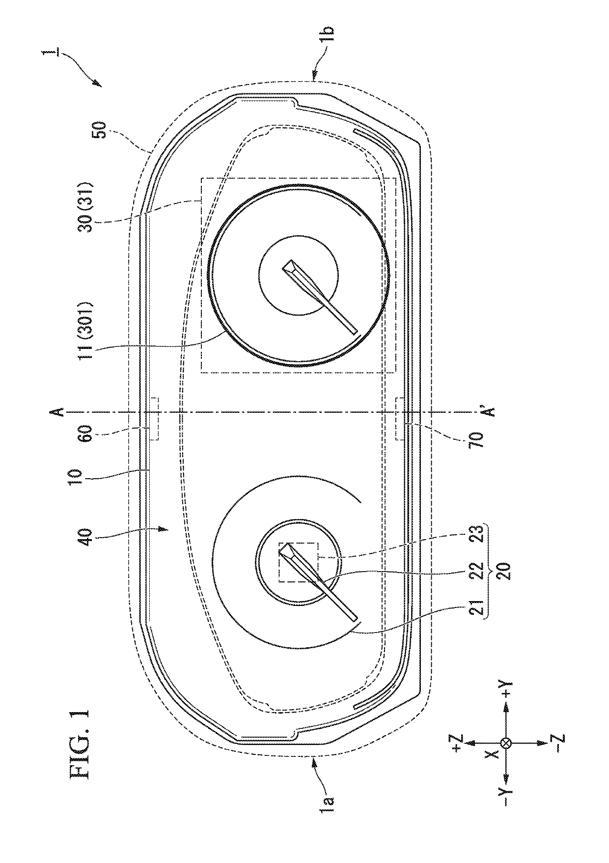
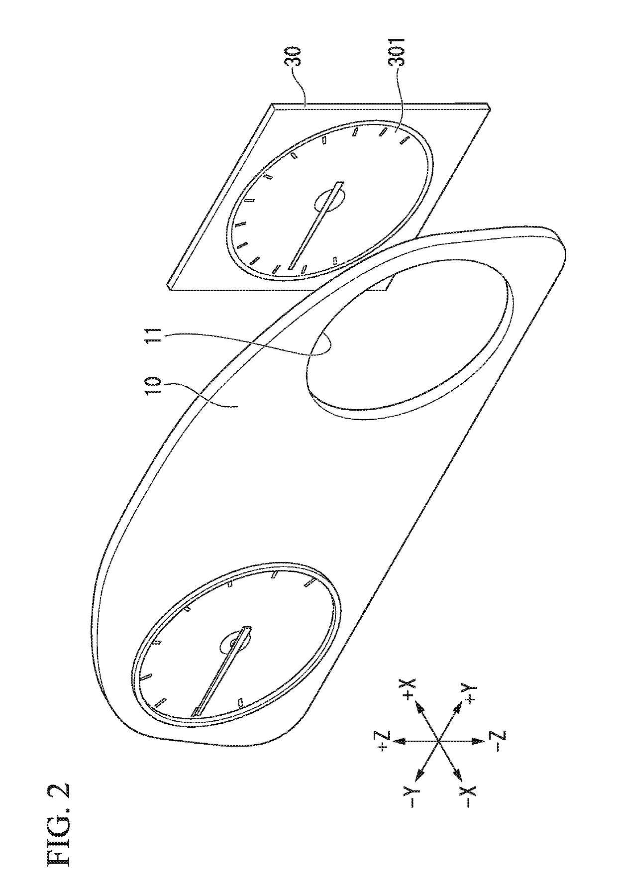
[0033]Hereinafter, an embodiment of the present invention will be described with reference to the drawings. FIG. 1 is a front view of a display device 1 according to an embodiment. FIG. 2 is a perspective view of the display device 1 according to the embodiment. The display device 1 is a device which adjusts a luminance of a display surface according to an amount of light radiated on the display surface. In the following embodiment, the display device 1 is mounted in a vehicle, displays information on the vehicle and provides the information to a driver, but the present invention is not limited thereto, and the display device 1 may be used for other purposes.

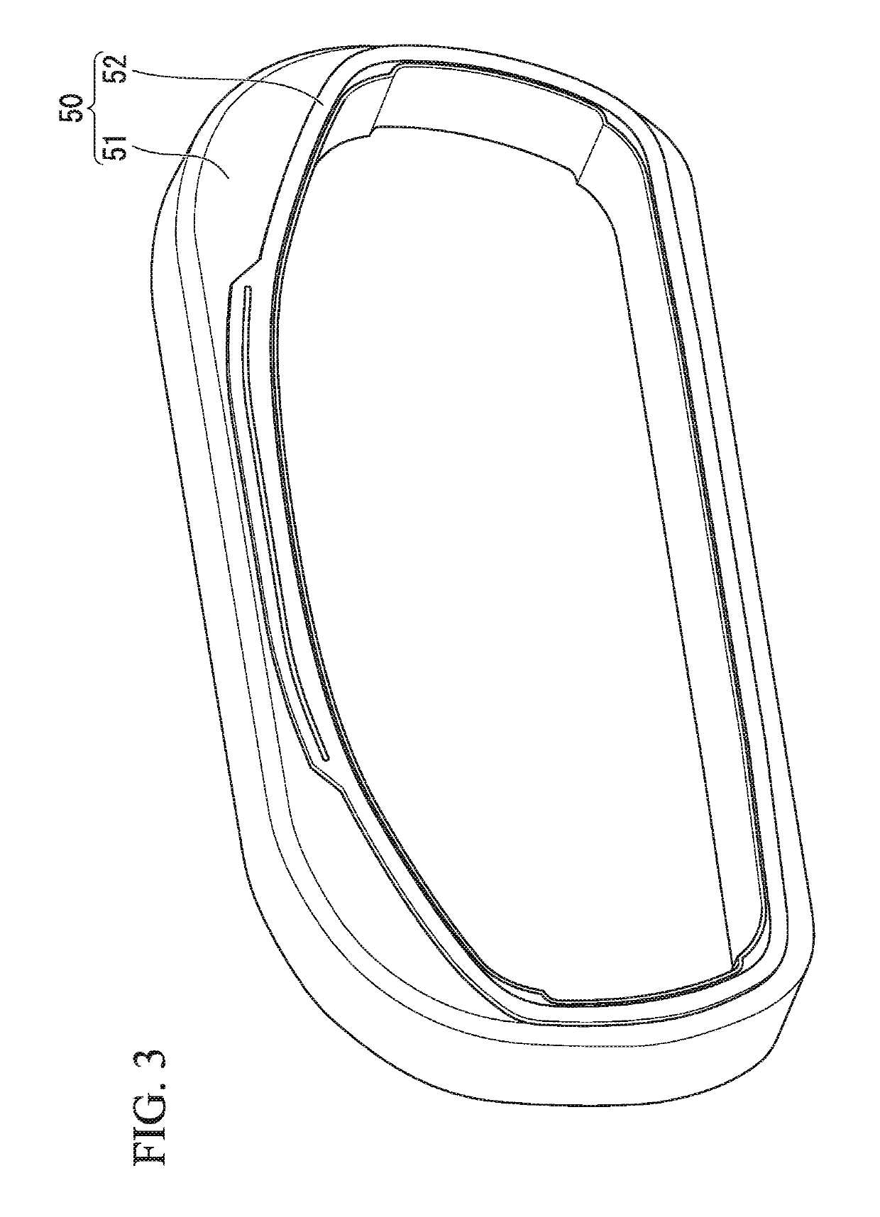
[0034]The display device 1 includes, for example, a display plate 10, an analog meter 20, a display panel 30, a cover 40, a decorative portion 50, an irradiator 60, and a light detector 70.

[0035]Here, an X direction, a Y direction, and a Z direction will be defined. The Y direction and the Z direction are directions along the di...

modified example

[0068]Hereinafter, a modified example of the embodiment will be described with reference to the drawing. FIG. 9 is a front view of a display device 2 according to a modified example. In the embodiment, the case in which the display device 1 includes the analog meter 20 and the display panel 30 has been described, but in the modified example, a case in which the display device 2 does not include the analog meter 20 and the display panel 30 but includes only the analog meter 20 will be described. Constituent elements similar to those of the above-described embodiment are designated by the same reference numerals, and description thereof will be omitted.

[0069]In the example shown in FIG. 9, the display device 2 does not include the display panel 30 and includes only the analog meter 20 (an analog meter 20a and an analog meter 20b shown in the drawing).

[0070]The analog meter 20a is provided on the left side as seen by the driver, and the analog meter 20b is provided on the right side as...


PUM


Abstract

There is provided a display device (1) including a display (30), a decorative portion (50) which covers an outer circumferential portion of the display, and a light detector (70) which is provided in contact with or in proximity to the decorative portion and is configured to detect an amount of light guided by the decorative portion.

Description

CROSS-REFERENCE TO RELATED APPLICATION[0001]Priority is claimed on Japanese Patent Application No. 2018-012047, filed Jan. 26, 2018, the content of which is incorporated herein by reference.BACKGROUND OF THE INVENTIONField of the Invention[0002]The present invention relates to a display device and a mounting structure of a vehicle meter.Description of Related Art[0003]Conventionally, a technique for displaying an image of a vehicle meter on a display instead of a mechanical vehicle meter is known (for example, Japanese Unexamined Patent Application, First Publication No. 2017-149182 and Japanese Unexamined Patent Application, First Publication No. 2006-329711).SUMMARY OF THE INVENTION[0004]A display (a display device) that shows a user an image by emitting light looks different according to the amount of external light. For example, in the case in which the amount of external light is large, for example, a case in which direct sunlight is incident, it is difficult to see an image wh...

Claims


Application Information

Patent Timeline
IPC IPC(8): B60Q3/18B60Q3/14G01D11/28B60Q3/51
CPCB60Q3/18B60Q3/14G01D11/28B60Q3/51B60K35/00B60K37/02B60K2370/698B60K2370/688B60K2370/336B60K2370/349B60K2370/48
Inventor KAWAKAMI, HAYATO
Owner HONDA MOTOR CO LTD
Why Eureka
Try Eureka