

Imaging lens and imaging device
a technology which is applied in the field of imaging lens and imaging device, can solve the problems of difficult to detect a far object, and achieve the effects of wide angle of view, reduced device size, and high resolution
- Summary
- Abstract
- Description
- Claims
- Application Information
AI Technical Summary
Benefits of technology
Problems solved by technology
Method used
Image

Examples
first embodiment
[0105](1) Configuration of Imaging Lens
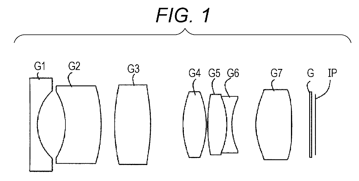
[0106]FIG. 1 is a lens cross-sectional view of a configuration of an imaging lens according to a first embodiment of the present invention. The imaging lens includes a first lens G1 which has negative refractive power and has a biconcave shape, a meniscus-shaped second lens G2 which has a concave surface facing to the object side and has negative refractive power, a third lens G3 which has positive refractive power and has a biconvex shape, a fourth lens G4 which has positive refractive power and has a biconvex shape, a cemented lens formed by bonding a fifth lens G5 which has positive refractive power and has a biconvex shape and a sixth lens G6 which has negative refractive power and has a biconcave shape, and a seventh lens G7 which has positive refractive power and has a biconvex shape in order from the object side. As indicated in Table 1 to be described later, both surfaces of the third lens G3, both surfaces of the fourth lens G4, and bo...
second embodiment
[0126](1) Configuration of Imaging Lens
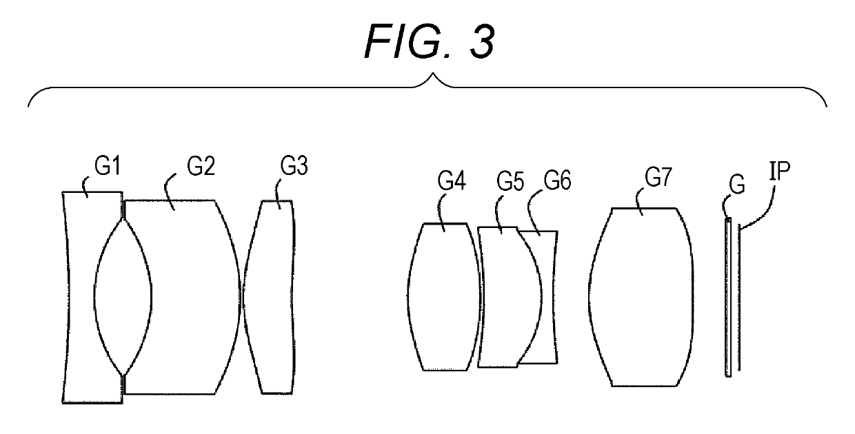
[0127]FIG. 3 is a lens cross-sectional view of a configuration of an imaging lens according to a second embodiment of the present invention. The imaging lens includes a first lens G1 which has negative refractive power and has a biconcave shape, a meniscus-shaped second lens G2 which has a concave surface facing to the object side and has negative refractive power, a third lens G3 which has positive refractive power and has a convex shape on the object side, a fourth lens G4 which has positive refractive power and has a biconvex shape, a cemented lens formed by bonding a fifth lens G5 which has positive refractive power and has a convex shape on the image side and a sixth lens G6 which has negative refractive power and has a biconcave shape, and a seventh lens G7 which has positive refractive power and has a biconvex shape in order from the object side. As indicated in Table 5 below, both surfaces of the second lens G2, both surfaces of the thi...
third embodiment
[0137](1) Configuration of Imaging Lens
[0138]FIG. 5 is a lens cross-sectional views of a configuration of an imaging lens according to a third embodiment of the present invention. The imaging lens includes a meniscus-shaped first lens G1 which has a convex surface facing to the object side, a meniscus-shaped second lens G2 which has a concave surface facing to the object side and has negative refractive power, a third lens G3 which has positive refractive power and has a biconvex shape, a fourth lens G4 which has positive refractive power and has a biconvex shape, a cemented lens formed by bonding a fifth lens G5 which has positive refractive power and has a biconvex shape and a sixth lens G6 which has negative refractive power and has a biconcave shape, and a seventh lens G7 which has positive refractive power and has a biconvex shape in order from the object side. As indicated in Table 9 below, both surfaces of the first lens G1, both surfaces of the third lens G3, both surfaces o...
PUM
 Abstract
Description
Claims
Application Information