Imaging apparatus

a technology of imaging apparatus and focusing operation, which is applied in the field of imaging apparatus, can solve the problems of difficult to precisely focus the imaging apparatus on the photographic subject, and achieve the effect of reducing the influence of wide angle image and comfortable focusing operation

Active Publication Date: 2022-01-25
KOKUSA ELECTRIC CO LTD
View PDF6 Cites 0 Cited by
  • Summary
  • Abstract
  • Description
  • Claims
  • Application Information

AI Technical Summary

Benefits of technology

[0012]According to the above-described imaging apparatus, a comfortable focusing operation can be achieved while an influence on a wide angle image is minimized.

Problems solved by technology

However, there is a problem in that, if the screen size of the viewfinder of an imaging apparatus used for checking an image that a photographer himself / herself takes is too small, or if it is difficult to check whether or not the imaging apparatus is focused on a photographic subject owing to the low resolution of the screen of the imaging apparatus, it becomes difficult to exactly focus the imaging apparatus on the photographic subject.

Method used


Image

  • Imaging apparatus
  • Imaging apparatus
  • Imaging apparatus

Examples


example 1

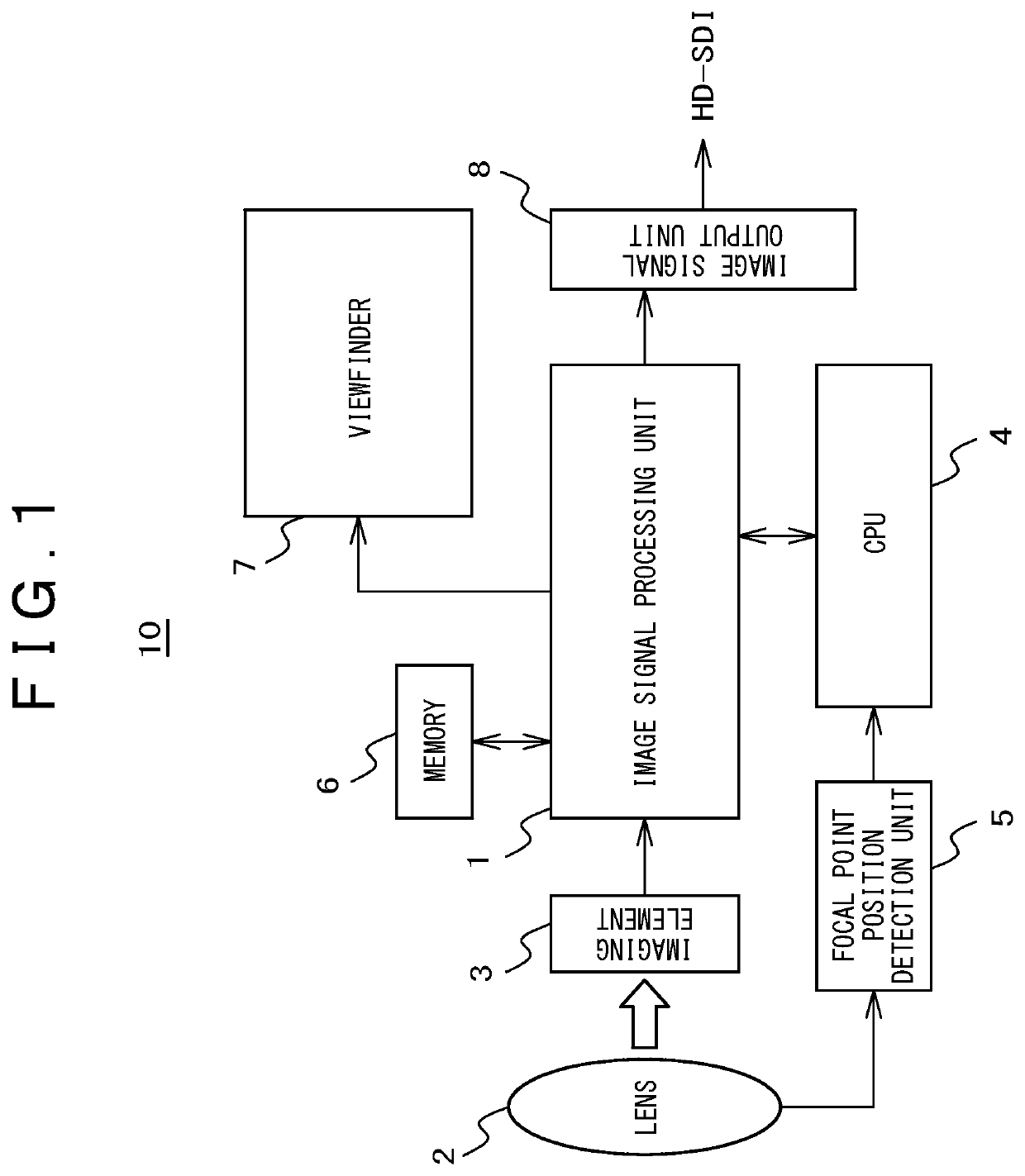
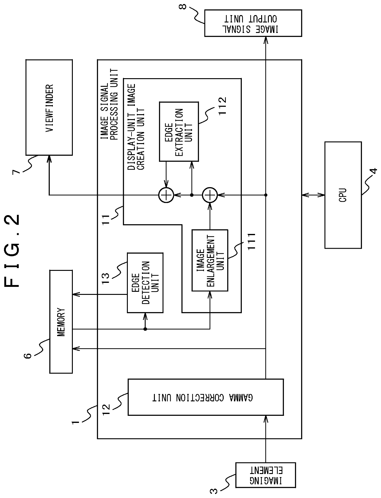
[0028]FIG. 1 is a block diagram showing a configuration example of an imaging apparatus according to Example 1.

[0029]FIG. 1 shows that an imaging apparatus 10 includes a lens 2, an imaging element 3, an image signal processing unit 1, a memory 6, a focal point position detection unit 5, a CPU (central processing unit) 4, an image signal output unit 8, and a viewfinder 7 that is a display unit.

[0030]Incident lights from a photographic subject focus into an image through the lens 2, and the image is photoelectrically converted into an electric signal by the imaging element 3. The image signal processing unit 1 executes various kinds of signal processing on the image signal and displays the image on the viewfinder 7, and at the same time an HD-SDI (high definition serial digital interface) signal is outputted from the image signal output unit 8. The CPU 4 controls the respective units of the imaging apparatus 10, and detects the movement of the focal point using a signal from the focal...

example 2

[0087]FIG. 12 and FIG. 13 are block diagrams showing a configuration example of an imaging apparatus according to Example 2.

[0088]In FIG. 12 and FIG. 13, the fundamental configuration of an imaging apparatus 10a is the configuration of a three-plate pixel shift camera. The imaging apparatus selects a visible light 22 or a near-infrared light 21 out of the visible light 22 and the near-infrared light 21 that enter the imaging apparatus itself using an optical selection filter 23. The optical selection filter 23 is configured to be capable of transmitting the visible light 22 or the near-infrared light 21. If the optical selection filter 23 is set so as to transmit the visible light 22, the visible light 22 is resolved into a red signal R, a green signal G, and a blue signal B by a wavelength resolution prism 24 on the basis of the wavelengths of these signals, and these signals are input into the installed sensors 25, 26, and 27 respectively. Sensors 25, 26, and 27 are fixed with the...


PUM


Abstract

An object of the present invention is to provide an imaging apparatus that can comfortably be focused while an influence on a wide angle image is minimized. The imaging apparatus includes: a display unit for displaying an image being photographed; an enlarged image display function for displaying an image obtained by enlarging a part of an area being photographed in the display unit; an edge component detection function for detecting an edge component amount of an enlarged image area; and a focal point position detection function for detecting movement of a focal point operated by a photographer. Duration time of the enlarged image display displayed by the enlarged image display function is changed in conjunction with the edge component detected by the edge component detection function and the movement of the focal point detected by the focal point position detection function.

Description

TECHNICAL FIELD[0001]The present invention relates to an imaging apparatus such as a digital video camera, and in particular relates to an imaging apparatus including an auxiliary display function suitable for checking the focused state of the imaging apparatus itself.BACKGROUND ART[0002]In recent years, photographers have been required to more exactly focus imaging apparatuses on photographic subjects as the resolutions of imaging apparatuses have become higher (for example, HD, 4K, 8K). However, there is a problem in that, if the screen size of the viewfinder of an imaging apparatus used for checking an image that a photographer himself / herself takes is too small, or if it is difficult to check whether or not the imaging apparatus is focused on a photographic subject owing to the low resolution of the screen of the imaging apparatus, it becomes difficult to exactly focus the imaging apparatus on the photographic subject.[0003]Therefore, various auxiliary display functions that mak...

Claims


Application Information

Patent Timeline
Patent Type & Authority Patents(United States)
IPC IPC(8): H04N5/232H04N5/33H04N5/14H04N5/262H04N5/345H04N3/16H04N1/14H04N1/40
CPCH04N5/232939H04N5/332G03B17/18G03B11/00G02B7/36H04N23/00H04N23/67H04N23/635H04N23/63H04N23/69H04N23/11H04N23/633
Inventor SHIBUYA, TAKUHIROIKEDA, SHIRO
Owner KOKUSA ELECTRIC CO LTD
Why Eureka
Try Eureka