Ultra wide field fundus imaging system

a fundus imaging and wide field technology, applied in the field of total reflection confocal scanning fundus imaging system, can solve the problems of affecting the imaging quality, the imaging field of the lens module imaging system is small, and the medical staff cannot meet the demand for wide field imaging, so as to achieve the effect of avoiding ghost images, wide field imaging, and improving imaging quality

Active Publication Date: 2020-03-03
SUZHOU MICROCLEAR MEDICAL INSTR
View PDF10 Cites 1 Cited by
  • Summary
  • Abstract
  • Description
  • Claims
  • Application Information

AI Technical Summary

Benefits of technology

[0006]The aim of the present invention is to provide an ultra wide field fundus imaging system, which can effectively avoid ghost images caused by lens module imaging and can achieve wide field imaging to improve the imaging quality.
[0017]Compared with the prior art, the benefits of the prevent invention as follows: the ultra wide field fundus imaging system realizes fundus imaging through total reflection and can effectively avoid ghost images caused by lens module imaging to improve the imaging quality. Since the curvature of the curved reflector 40 is gradually changed, so the light reflected by the curved reflector 40 can enter in the fundus at a larger incident angle (achieving 100°˜180° fundus perspective imaging), thereby achieving wide field imaging.

Problems solved by technology

However, the lens module likely to reflect the illumination light to form a ghost image, affecting the imaging quality.
In addition, the imaging field of the lens module imaging system is small and can not satisfy the medical staff's demand for wide field imaging.

Method used


Image

  • Ultra wide field fundus imaging system

Examples


Embodiment Construction

[0019]In order to clear the purpose, the technical scheme and the advantages of the invention, reference will now be made to the drawing FIGURES to describe the embodiments of the present disclosure in detail.

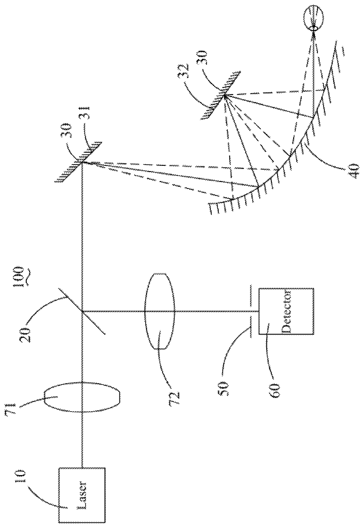
[0020]Referring to FIG. 1, the present invention an ultra wide field fundus imaging system 100 comprises a photosource 10, an optical splitter 20, a scanning assembly 30, a curved reflector 40 arranged opposite to the scanning assembly 30, a probe pinhole 50 and an imaging assembly 60. The scanning assembly 30 includes a first scanning mirror 31 scanning along a first direction and a second scanning mirror 32 scanning along a second direction; the first direction is orthogonal to the second direction. The light emitted by the photosource 10 passes through the optical splitter 20, then reflected by the first scanning mirror 31, the curved reflector 40, the second scanning mirror 32 and the curved reflector 40 respectively, and then enters in the fundus. The light entering the fu...


PUM

PropertyMeasurementUnit
trajectoryaaaaaaaaaa
rotation angleaaaaaaaaaa
unit timeaaaaaaaaaa

Abstract

An ultra wide field fundus imaging system comprises a photosource, an optical splitter, a scanning assembly, a curved reflector, a probe pinhole and an imaging assembly. The scanning assembly includes a first scanning mirror scanning along a first direction and a second scanning mirror scanning along a second direction. The light emitted by the photosource passes through the optical splitter, then successively is reflected by the first scanning mirror, the curved reflector, the second scanning mirror and the curved reflector, and then enters in the fundus; the light entering the fundus is reflected by the retina and then successively is reflected by the curved reflector, the second scanning mirror, the curved reflector, the first scanning mirror and then returned to the optical splitter; the light is reflected by the optical splitter and passes through the probe pinhole, finally the light enters in the imaging assembly. Compared with the prior art, the ultra wide field fundus imaging system realizes fundus imaging by total reflection and can effectively avoid ghost images caused by lens module imaging to improve the imaging quality. Since the curvature of the curved reflector is gradually changed, so the light reflected by the curved reflector can enter in the fundus at a larger incident angle to achieve wide field imaging.

Description

CROSS-REFERENCE TO RELATED APPLICATIONS[0001]This application claims priority to Chinese Application Serial No. 201610984986.X, filed Nov. 9, 2016, the disclosures of which are hereby incorporated by reference in their entirety.TECHNICAL FIELD[0002]The present invention generally relates to fundus imaging system, and more particularly to a total reflection confocal scanning fundus imaging system.BACKGROUND[0003]The fundus camera belongs to medical imaging field, is used for obtaining human retina images to assist medical staff checking fundus diseases and judging the condition of other organs. Because only fundus veins can directly observe through body surface, the medical staff can check the optic nerve, retina, choroid and refractive media in the fundus by the fundus camera to identify the fundus condition, at the same time, the fundus camera can assist to diseases diagnosis and disease judgment for other organ systems, such as: the retina can be used to detect cerebral infarction...

Claims


Application Information

Patent Timeline
Patent Type & Authority Patents(United States)
IPC IPC(8): A61B3/14G02B27/14A61B3/12G02B26/10G02B27/00G02B5/10A61B3/00A61B3/103A61B3/10
CPCG02B27/0081G02B27/141G02B26/101G02B27/144A61B3/103A61B3/14A61B3/1025G02B5/10A61B3/12A61B3/0016G02B17/08G02B26/105G02B27/0018
Inventor LI, CHAOHONG
Owner SUZHOU MICROCLEAR MEDICAL INSTR
Why Eureka
Try Eureka