Camera module

a technology of camera module and camera body, which is applied in the field of camera module, can solve the problems of easy formation of minute irregularities in staining processing, and achieve the effect of relative easy manufacturing and same shape stability

Inactive Publication Date: 2007-03-08
MITSUMI ELECTRIC CO LTD
View PDF5 Cites 13 Cited by
  • Summary
  • Abstract
  • Description
  • Claims
  • Application Information

AI Technical Summary

Benefits of technology

[0023] According to the camera module having the above structure, a mold for forming the barrel can be manufactured with r

Problems solved by technology

Therefore, minute irregularities for staining processing ca

Method used


Image

  • Camera module
  • Camera module
  • Camera module

Examples


first embodiment

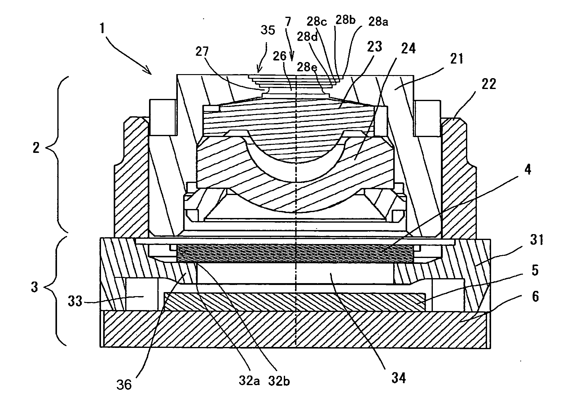
[0029] Hereinbelow, a camera module 1 according to the present invention will be described in detail with reference to the appended drawings. In this regard, it is to be noted that since the camera module 1 is to be equipped in small electronic apparatuses, such as, for example, cellar phones, it has a particularly compact size, for example, 6 mm in length, 6 mm in width and 4.5 mm in height.

[0030]FIG. 1 illustrates a cross sectional view of the camera module 1 according to a first embodiment of the present invention. The camera module 1 is composed of a lens unit 2 having an objective lens 23 and a lens 24, and an image pickup device portion 3 provided under the lens unit 2 and having an image pickup device housing space 33 in which an image pickup device (that is, a CMOS sensor) 5 is hermetically provided.

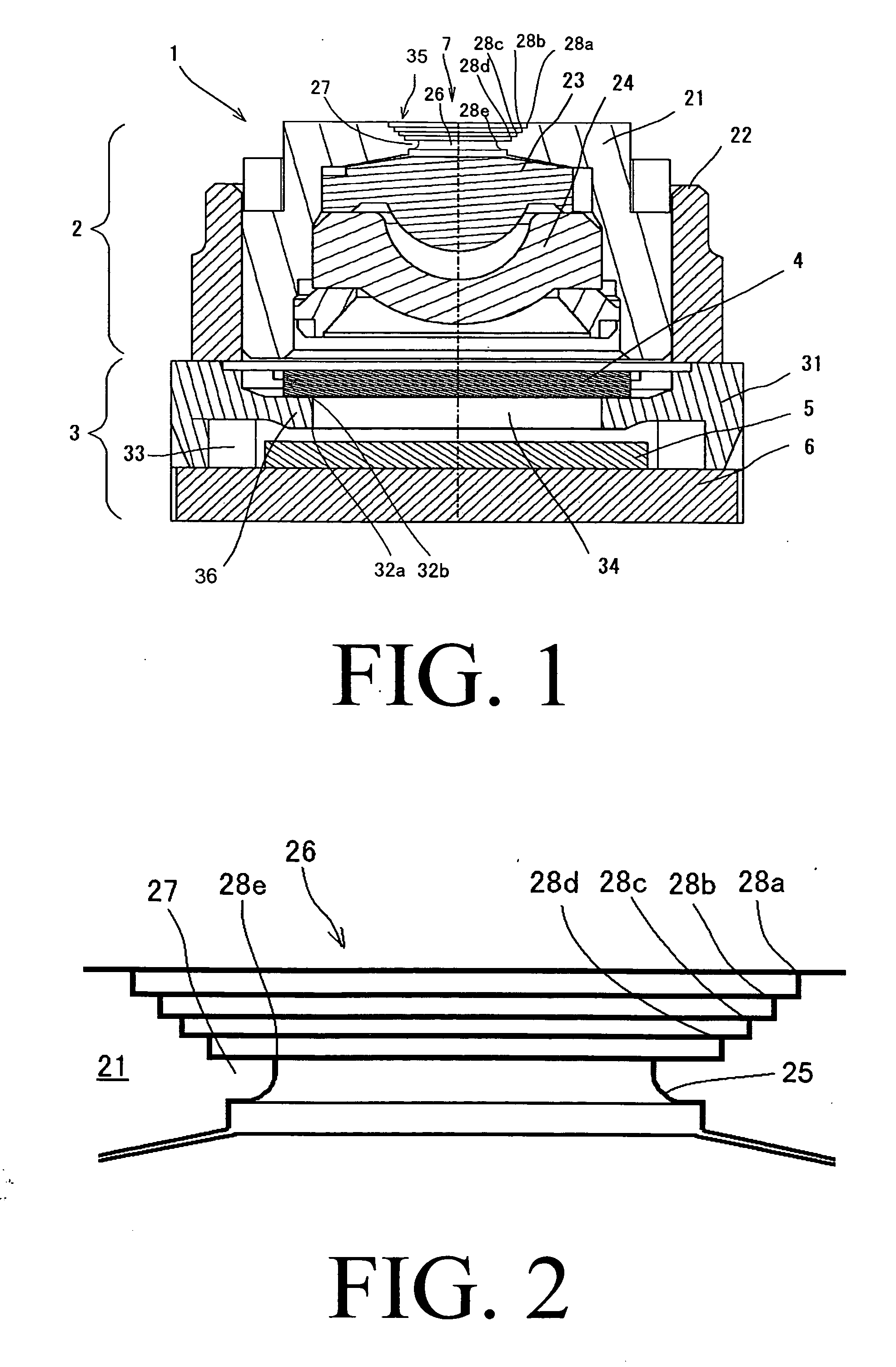
[0031] In more details, the lens unit 2 has the objective lens 23, the lens 24 and a barrel 21 provided with the objective lens 23 and the lens 24. The barrel 21 has a barrel op...

second embodiment

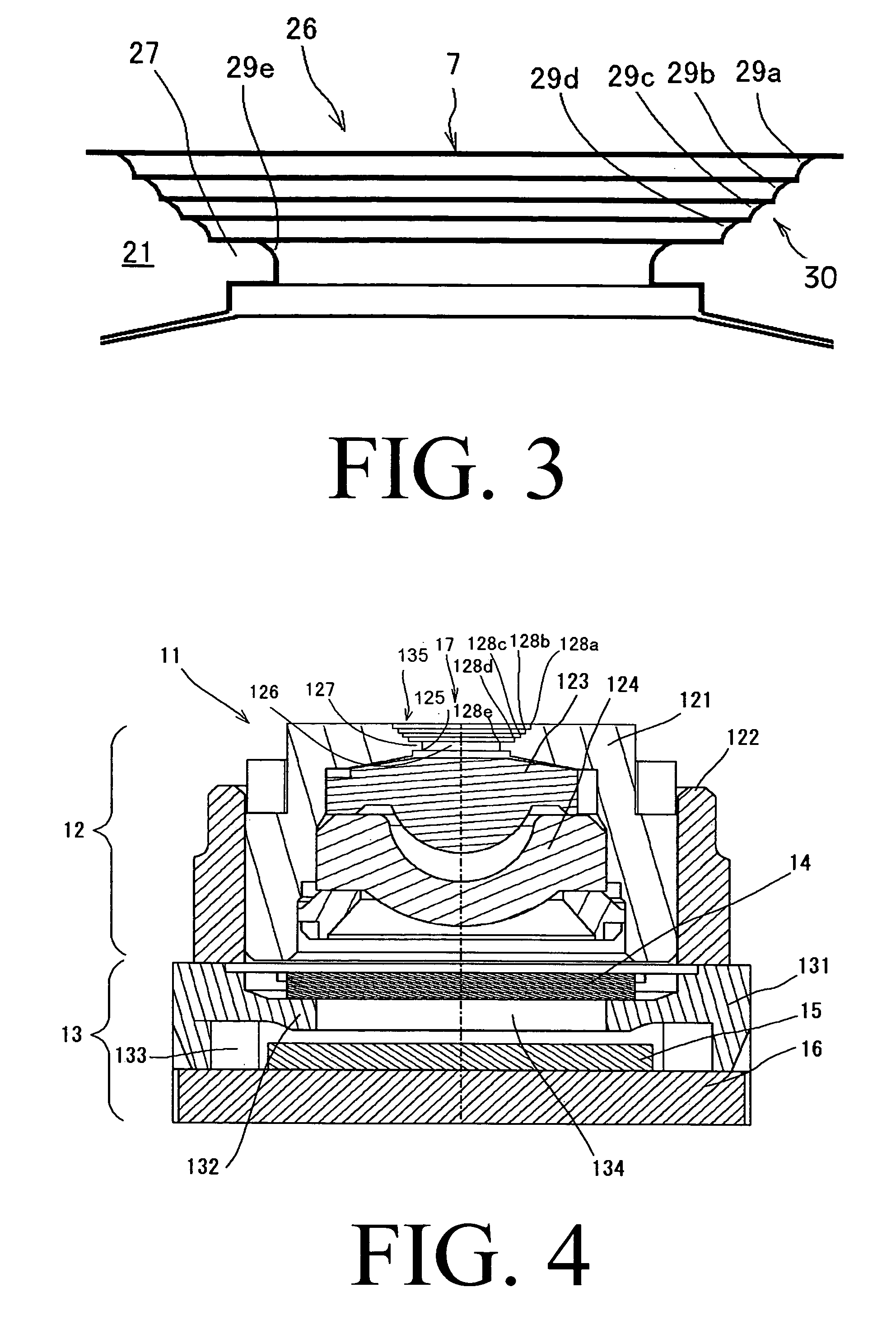
[0041] In a barrel opening 26 of a camera module of the second embodiment, an outside opening portion 30 is formed to provide a shallow conical shape having an inclined surface diverging from an edge 27 inward with respect to the outside of the barrel 21. On the conically inclined surface of the barrel opening 26, steps (step portions) 29a-29e are formed in a stair-like manner. These steps 29a-29e in the step positions are provided on the inner peripheral surfaces defining or surrounding the light path 7 so as to protrude toward the light path 7.

[0042] Each of the steps 29a-29e is formed to have a rounded cross-sectional shape which forms a roughly arc-shape of about 90 degrees and minute irregularities with staining are also formed on the surface of each of the steps 29a-29e. In this regard, it is to be noted that the outside opening 30 formed with these steps is also a portion of the camera module where undesirable stray light is likely to be generated, because external light ente...


PUM


Abstract

A camera module is composed from a lens unit including at least one lens, a barrel provided with the lens and having a barrel opening, and a lens holder for holding the barrel; and an image pickup device portion provided under the lens unit and having an image pickup device housing space in which an image pickup device is hermetically provided. The barrel opening of the barrel has an annular edge which serves as a diaphragm, and the annular edge of the barrel opening has a lower annular corner portion which is located on the side of the lens, wherein the lower annular corner portion of the annular edge is formed so as to have a rounded cross-sectional shape and staining is formed on the lower annular corner portion.

Description

[0001] This application claims priority to Japanese Patent Application No. 2005-258498 filed Sep. 6, 2005, which is hereby expressly incorporated by reference herein in its entirety. BACKGROUND OF THE INVENTION [0002] 1. Field of the Invention [0003] The present invention relates to a camera module, and more specifically to a camera module having a relatively compact size to be equipped in camera-equipped electronic apparatuses, such as, for example, a cellular phones and the like. [0004] 2. Description of the Prior Art [0005] In a camera module having a relatively compact size to be equipped in camera-equipped electronic apparatuses, such as, for example, cellular phones and / or the like, a CMOS sensor or a CCD sensor is used as an image pickup device. [0006]FIG. 4 is a cross sectional view showing a prior art camera module 11. The camera module 11 is composed of a lens unit 12 and an image pickup device portion 13 provided under the lens unit 12. [0007] The lens unit 12 includes a ...

Claims


Application Information

Patent Timeline
IPC IPC(8): G03B17/00
CPCG02B5/003G02B13/001G02B27/0018H04N5/2254G03B29/00H04N5/2253G03B17/02H01L27/14618H01L27/14625H04N23/55H04N23/54
Inventor SHIBATA, HISASHISATO, TOSHIHIKO
Owner MITSUMI ELECTRIC CO LTD
Why Eureka
Try Eureka