Member having antireflection structure

a member and anti-reflection technology, which is applied in the field of members having anti-reflection structures, can solve the problems of abnormal changes in the refractive index of incident light at the inner walls of the aperture diaphragm, the inability to achieve excellent anti-reflection at the entire range of visible light, and the need for imaging optical devices, so as to prevent unnecessary reflection of light, suppress the occurrence of stray light, and suppress ghost and flare

Inactive Publication Date: 2006-10-12
PANASONIC CORP
View PDF10 Cites 15 Cited by
  • Summary
  • Abstract
  • Description
  • Claims
  • Application Information

AI Technical Summary

Benefits of technology

[0018] The present invention can provide a member capable of preventing the reflection of unnecessary light and sufficiently suppressing the occurrence of stray light even in a compact optical apparatus, and suited as a component member or the like for holding an optical element disposed in an optical path. Furthermore, ghost and flare can be suppressed sufficiently by applying the member to optical apparatuses, more particularly, to imaging optical devices. Hence, it is possible to realize imaging optical devices being excellent in image characteristics.

Problems solved by technology

The stray light causes ghost and flare, thereby degrading image quality.
However, such a method requires complicated processes to accurately control the optical film thickness of the antireflection film, thereby being desired to be improved in productivity and cost.
In particular, it is very difficult to attain excellent antireflection at the entire range of visible light, required in imaging optical devices.
However, in recent years, as imaging optical devices become more compact, the refractive index of the incident light at the inner walls of the aperture portions in the aperture diaphragm and the lens-holding member changes abnormal, and the distribution of the refractive index at the optically functioning face does not change smoothly.
As a result, unnecessary light is reflected slightly, and ghost and flare occur, thereby causing a problem of degrading image characteristics.

Method used


Image

  • Member having antireflection structure
  • Member having antireflection structure
  • Member having antireflection structure

Examples


Embodiment Construction

[0030] A member having an antireflection structure in accordance with an embodiment of the present invention will be described below. The member having the antireflection structure is applicable as a component member in various kinds of optical apparatuses, for example. An aperture of a camera lens is herein taken as an example and described below.

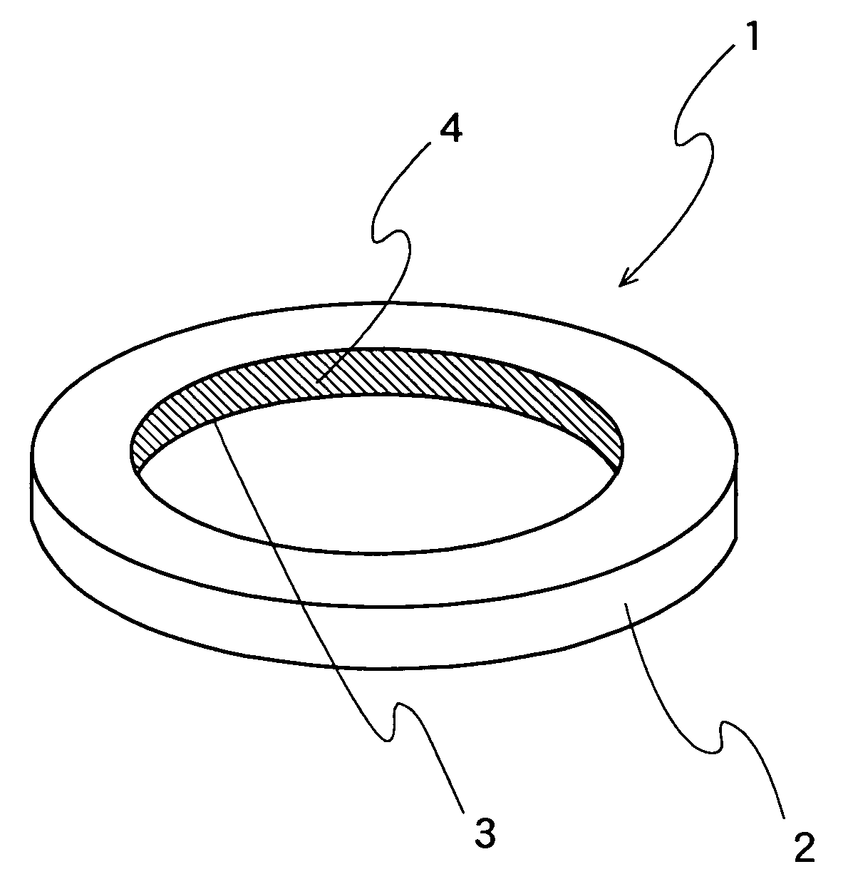
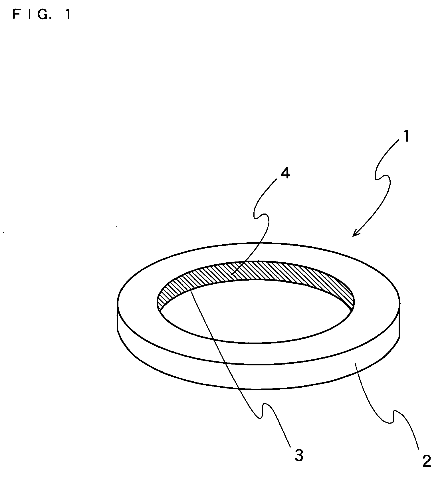
[0031]FIG. 1 is a schematic perspective view showing the configuration of the aperture of a camera lens. In FIG. 1, the aperture 1 comprises a plate-like portion 2 having a thickness, and an aperture portion 3 formed in the plate-like portion 2.

[0032] In the present embodiment, it is preferable that the width of an inner wall 4 (the shaded area in FIG. 1) of the aperture portion 3 is 0.03 mm or more and 1 mm or less. The width of the inner wall 4 of the aperture portion 3 is also defined as the thickness of the plate-like portion 2. If the width of the inner wall 4 is less than 0.03 mm, it is difficult to form the aperture portion 3 in t...


PUM


Abstract

A reflection of unnecessary light, which should be prevented, can be suppressed, and occurrence of stray light can be reduced using a member having an antireflection structure, comprising a plate-like portion 2, and an aperture portion 3 formed in the plate-like portion 2, wherein the antireflection structure having an aspect ratio of 1 or more and comprising structural elements arranged in an array form at a period smaller than the shortest wavelength of light, the reflection of which should be prevented, is formed on an inner wall 4 of the aperture portion 3.

Description

CROSS-REFERENCE TO RELATED APPLICATION [0001] This application is based on application No. 2005-63786 filed in Japan on Mar. 8, 2005, the content of which is hereby incorporated by reference. BACKGROUND [0002] 1. Technical Field [0003] The present invention relates to a member having an antireflection structure. More particularly, the present invention relates to a member having an antireflection structure capable of improving the image characteristics of optical apparatuses, for example. [0004] 2. Description of the Background Art [0005] Most of optical elements and optical components being used for various uses are requested to have an antireflection function to prevent the reflection of light. FIG. 5 is a schematic cross-sectional view showing the configuration of an imaging optical device being used generally and also showing the cross-sectional structure of an imaging optical device 50 along a plane including an optical axis 51. In FIG. 5, an aperture diaphragm 53, a lens eleme...

Claims


Application Information

Patent Timeline
Patent Type & Authority Applications(United States)
IPC IPC(8): H01S5/00
CPCG02B1/118G02B7/02G02B5/003G02B1/12
Inventor YOSHIKAWA, MOTONOBUYOSHITSUGU, KEIKIOKAYAMA, HIROAKIYAMAMOTO, YOSHIHARUBOKU, KAZUTAKE
Owner PANASONIC CORP
Why Eureka
Try Eureka