High-Low Pulley Rack System for Weight Machine

a pulley rack and weight machine technology, applied in the field of exercise or weight machines, can solve the problems of inability to mount to the cable exercise machine, limited cable exercise machine, and additional components

Active Publication Date: 2019-08-08
SPECIALTY FITNESS SYST
View PDF32 Cites 28 Cited by
  • Summary
  • Abstract
  • Description
  • Claims
  • Application Information

AI Technical Summary

Benefits of technology

[0016]According to another non-limiting aspect of the disclosure, the pulley rack further includes a safety spotter arm mounted to the upright above the cable end assembly and adapted to prevent the barbell from dropping below a second predetermined height.
[0025]According to another non-limiting aspect of the disclosure, the pulley rack further includes a safety spotter arm mounted to the upright above the cable end assembly and adapted to prevent the barbell from dropping below a second predetermined height.
[0037]Clause 7: The pulley rack of any of clauses 1 to 6, further comprising a safety spotter arm mounted to the upright above the cable end assembly, the safety spotter arm adapted to prevent the barbell from dropping below a second predetermined height.
[0046]Clause 16: The pulley rack of any of clauses 10 to 15, further comprising a safety spotter arm mounted to the upright above the cable end assembly, the safety spotter arm adapted to prevent the barbell from dropping below a second predetermined height.

Problems solved by technology

However, existing cable exercise machines are limited in that additional components necessary to perform certain exercises, such as bar catches needed for a barbell chess press, cannot be mounted to the cable exercise machine because the pull cable obstructs much of the support frame.

Method used


Image

  • High-Low Pulley Rack System for Weight Machine
  • High-Low Pulley Rack System for Weight Machine
  • High-Low Pulley Rack System for Weight Machine

Examples


Embodiment Construction

[0064]For purposes of the description hereinafter, the terms “upper”, “lower”, “right”, “left”, “vertical”, “horizontal”, “top”, “bottom”, “lateral”, “longitudinal”, and derivatives thereof shall relate to the disclosure as it is oriented in the figures. However, it is to be understood that the disclosure may assume alternative variations and step sequences, except where expressly specified to the contrary. It is also to be understood that the specific devices and processes illustrated in the attached drawings, and described in the following specification, are simply exemplary aspects of the disclosure. Hence, specific dimensions and other physical characteristics related to the aspects disclosed herein are not to be considered as limiting.

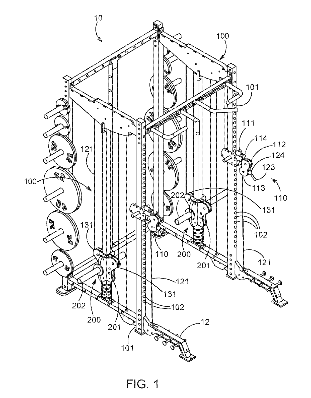
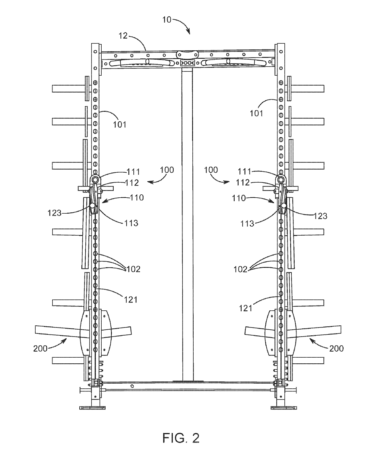
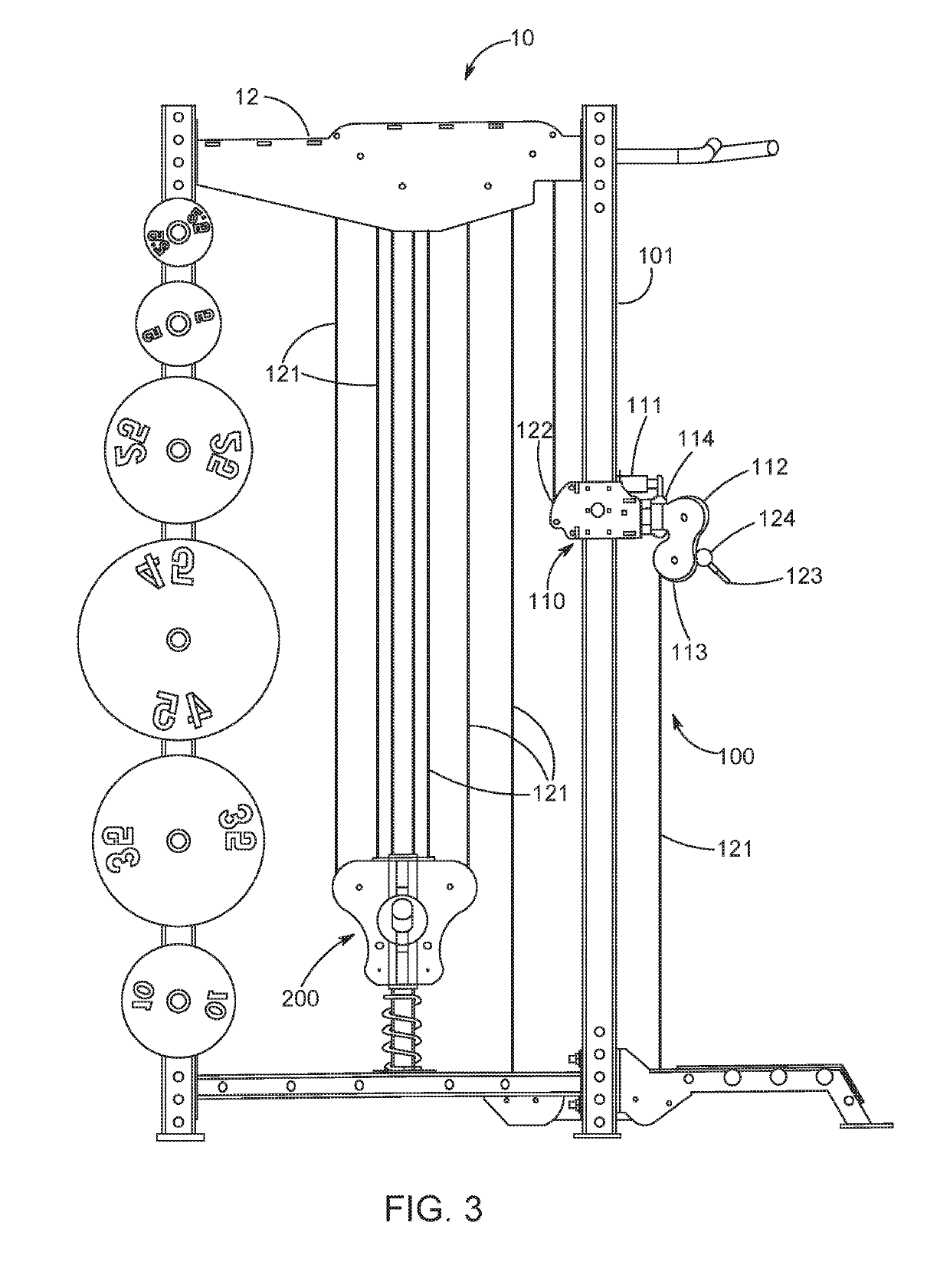
[0065]The present disclosure relates generally to exercise or weight machines and, more particularly, to an adjustable high-low pulley rack that allows a user to vary the location of a pull cable for performing exercises on a cable exercise or wei...


PUM


Abstract

A pulley rack for an exercise machine includes a support frame, an upright extending generally vertically within the support frame, a counterweight having one or more counterweight pulleys, the counterweight moveable in a vertical direction relative to the support frame, one or more guide pulleys mounted to the support frame, a cable end assembly mounted to the upright, and a pull cable having a fixed attachment end connected to the cable end assembly and a pullable end freely passing through the cable end assembly. The pull cable is routed through the cable end assembly, the counterweight pulleys, and guide pulleys such that a force exerted on the pullable end raises the counterweight. A section of the pull cable extends from the pullable end through the cable end assembly and downwardly to one of the guide pulleys mounted below the cable end assembly.

Description

CROSS-REFERENCE TO RELATED APPLICATION[0001]This application claims priority to U.S. Provisional Patent Application No. 62 / 422,350 filed Nov. 15, 2016, the disclosure of which is hereby incorporated in its entirety by reference.BACKGROUND OF THE INVENTIONField of the Invention[0002]This disclosure relates generally to exercise or weight machines and, more particularly, to an adjustable pulley rack system that allows a user to vary the location of a pull cable for performing exercises on a cable exercise machine.Description of Related Art[0003]Exercise machines which employ a cable and pulley system attached to a counterweight are well known. Conventionally, cable exercise machines include a support frame to which a moveable counterweight and one or more pulley are mounted. A cable extends vertically from the top of the counterweight and is routed through the one or more pulleys to a free end of the cable. Various attachments, such as D-handles, barbells, or rope handles, may be atta...

Claims


Application Information

Patent Timeline
Patent Type & Authority Applications(United States)
IPC IPC(8): A63B21/062A63B21/072A63B21/078A63B21/00
CPCA63B21/0624A63B21/0628A63B21/0724A63B21/0783A63B21/156A63B2225/09A63B2225/102A63B21/075A63B21/078A63B23/03566A63B21/00065A63B21/0632A63B21/4029
Inventor LEIPHEIMER, JERRY K.
Owner SPECIALTY FITNESS SYST
Why Eureka
Try Eureka