
Attachment mechanism

Inactive Publication Date: 2019-08-08
ROTTEFELLA AS
View PDF0 Cites 0 Cited by
  • Summary
  • Abstract
  • Description
  • Claims
  • Application Information

AI Technical Summary

Benefits of technology

The patent describes a shoe attachment mechanism that has pins and guides for easy installation and adjustment. The pins are designed to cooperate with complementary retaining means for secure attachment. The attachment mechanism also includes forcing means to control the pins' engagement with the retaining means. This mechanism allows for easy and customizable attachment of shoes to a variety of situations.

Problems solved by technology

Owing to the limitations given, inter alia, by the width of the ski shoe tip, the width of the ski binding and the width of the ski, the width of the exposed metal bar has typically been limited to about 3 cm.
This solution is substantially heavier and bulkier.
Although the design and material of ski bindings have been developed such that there has been a steady improvement in torsional rigidity, the width limitation has constituted a limitation to any substantial increase of torsional rigidity in connection with ski shoes and the ski binding / ski.
The width limitations have also been related to a need to have a uniform width that fits all shoe sizes from the smallest to the largest.
An unduly large width would either have resulted in children's ski shoes being impractically wide at the front of the shoe, which would have represented a limitation on the smallest safe or practical shoe size that could be produced for children.
The alternative could have been to offer different widths for different shoe sizes, but this would have resulted in a simultaneous need for different binding sizes, which both the consumer and binding manufacturers regard as being a major drawback.
Today's solutions also impose limitations on the design and function of the ski binding itself.
The drawbacks of the “duckbill” solutions comprised, inter alia, an unfavourably positioned axis of rotation, rapid wear / breaks and little torsional rigidity.
Although today's commercially available binding solutions have weaknesses, they are a result of an evolution of earlier solutions, such that in comparison with historical solutions they are significantly better.
US 2004 / 01140647 A1 does not appear to address the problem of torsional rigidity,—which can perhaps be said to be poorer than the prior art described above.
In addition, the system forms a relatively complex binding with many movable and exposed parts.
However, there remain a number of problems associated with making an attachment mechanism for skiing where detached heels are used.
In skiing it is a known issue that icing and condensation can cause problems for mechanical components.

Method used


Image

  • Attachment mechanism
  • Attachment mechanism
  • Attachment mechanism

Examples


Embodiment Construction

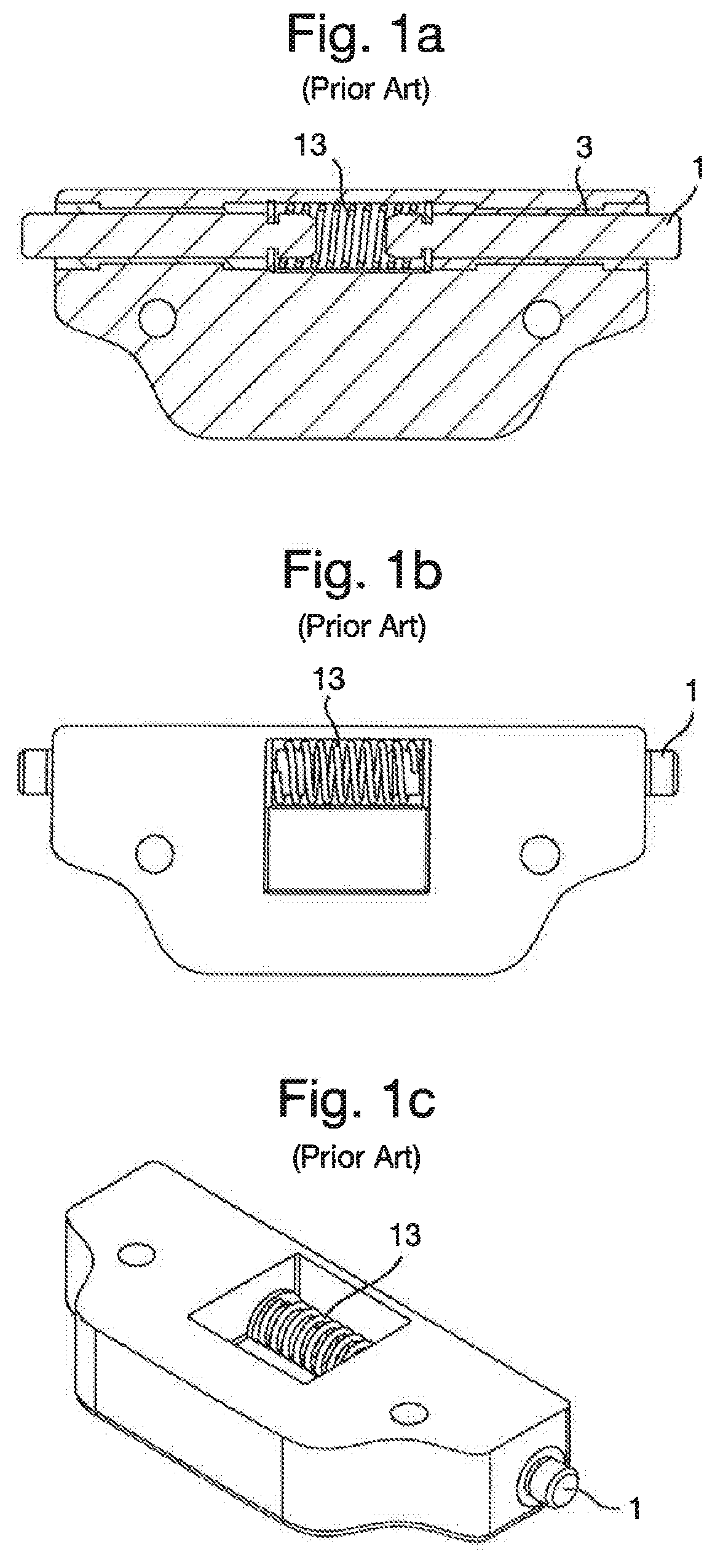
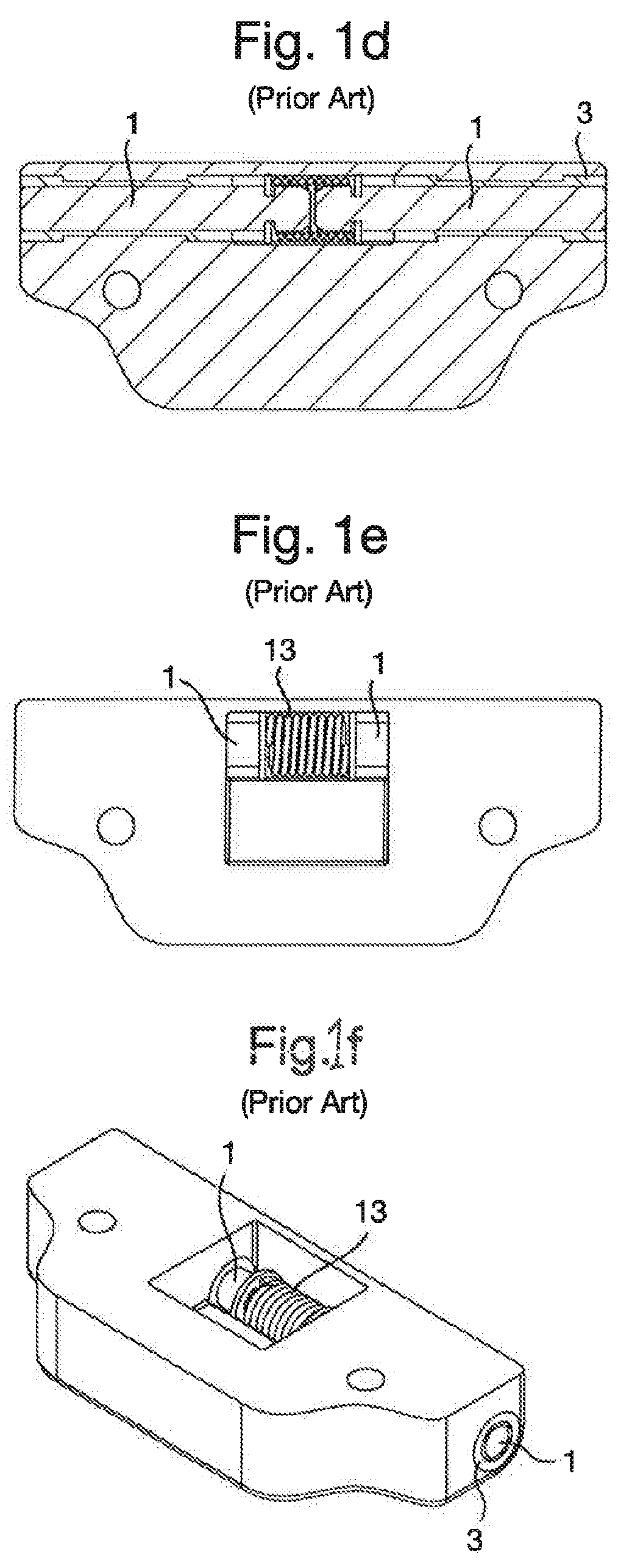
[0044]FIGS. 1a-f show prior art. A spring 13 is arranged such that it biases the pins 1 and presses them outwards. To press the pins inwards, they are squeezed together using the fingers, optionally via button sleeves that act as guides (not shown).

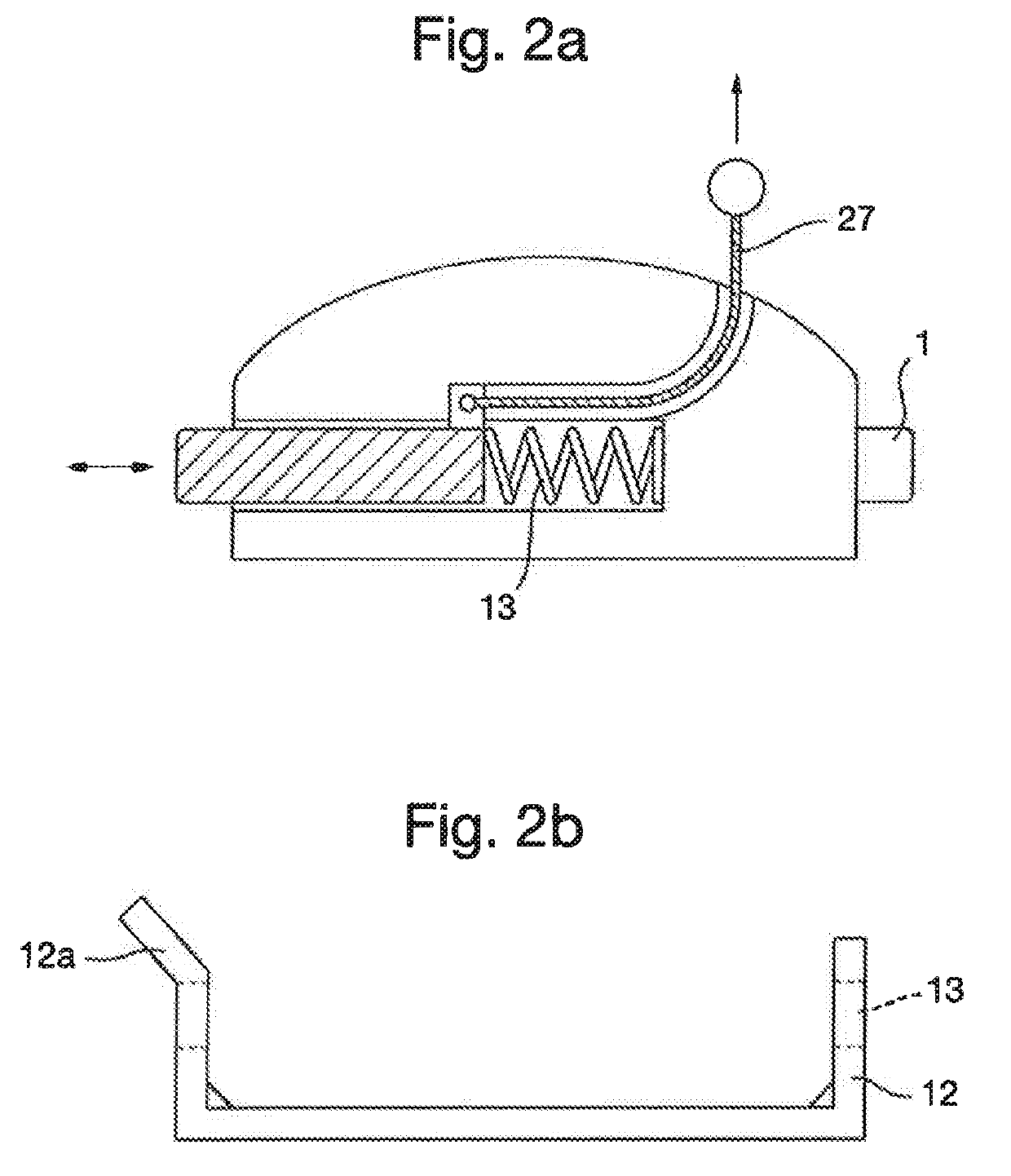
[0045]FIGS. 2a-b show a possible embodiment of the invention. The embodiment comprises a cord 27 that can be used to squeeze together a squeezing mechanism. The squeezing mechanism is designed to overcome a biasing force from a spring. In the embodiment shown in FIG. 1 a, the spring 13 forces one of the pins 1 outwards, whilst the other pin 1 projects statically. It will be understood that both pins 1 can be displaceable in an alternative embodiment, the spring 13 then forcing both pins 1 outwards in a starting position. In that case the squeezing mechanism will help to force both pins 1 together when it is operated or actuated. The cord 27 may also be made in the form of a loop and may comprise a wire 18, with or without sleeving. By pul...


PUM


Abstract

The present invention relates to an attachment mechanism for a shoe, the attachment mechanism comprising at least two pins (1), one on each side of the shoe, where the pins (1) are arranged in their respective guides (3), the pins (1) being designed to cooperate with a complementary retaining means (12). The attachment mechanism is, inter alia, characterised in that the attachment mechanism further comprises forcing means that are designed to force the pins (1) outwards into engagement with the complementary retaining means (12), and inwards out of engagement with the complementary retaining means (12).

Description

[0001]The invention relates to an attachment mechanism for a ski shoe with detached heel for various types of skiing and other uses where a shoe is to be attached to another article.PRIOR ART[0002]Today different types of bindings are used for the different types of skiing. In the type of skiing where the heel must be detached to facilitate or optimise propulsion, e.g., diagonal stride, skating, ski games for children, backcountry etc., there are a small number of commercially available binding solutions. These binding solutions are characterised in that a ski shoe comprises a metal bar under or immediately in front of the ski shoe tip, which bar fits into and can be secured to a binding that is arranged on or in a ski. The metal bar is typically arranged transversely between two end blocks, which end blocks form a part of the sole and / or shoe tip of the ski shoe.[0003]Owing to the limitations given, inter alia, by the width of the ski shoe tip, the width of the ski binding and the ...

Claims


Application Information

Patent Timeline
IPC IPC(8): A63C9/16A63C9/10A63C9/08A63C9/086A43B5/04
CPCA63C9/16A63C9/10A63C9/0802A63C9/086A43B5/0421A43B5/0423A63C9/02A63C9/08A63C9/0885A63C9/18A63C9/20A63C9/22
Inventor SVENDSEN, OYVARGOVERUD-HOLM, THOMASHOLOS, STEINARDANIELSEN, JORN FRODE
Owner ROTTEFELLA AS
Learn More