Vehicle turning control apparatus

Active Publication Date: 2019-08-08
NTN CORP
View PDF0 Cites 12 Cited by
  • Summary
  • Abstract
  • Description
  • Claims
  • Application Information

AI Technical Summary

Benefits of technology

[0006]An object of the present invention is to provide a vehicle turning control device that enables immediate stabilization of the vehicle attitud

Problems solved by technology

Therefore, estimation for the road surface frictional coefficient is delayed, so that the vehicle might become unstable due to yaw moment control.
In addition, in the case where a braking/driving force is applied b

Method used


Image

  • Vehicle turning control apparatus
  • Vehicle turning control apparatus
  • Vehicle turning control apparatus

Examples


Embodiment Construction

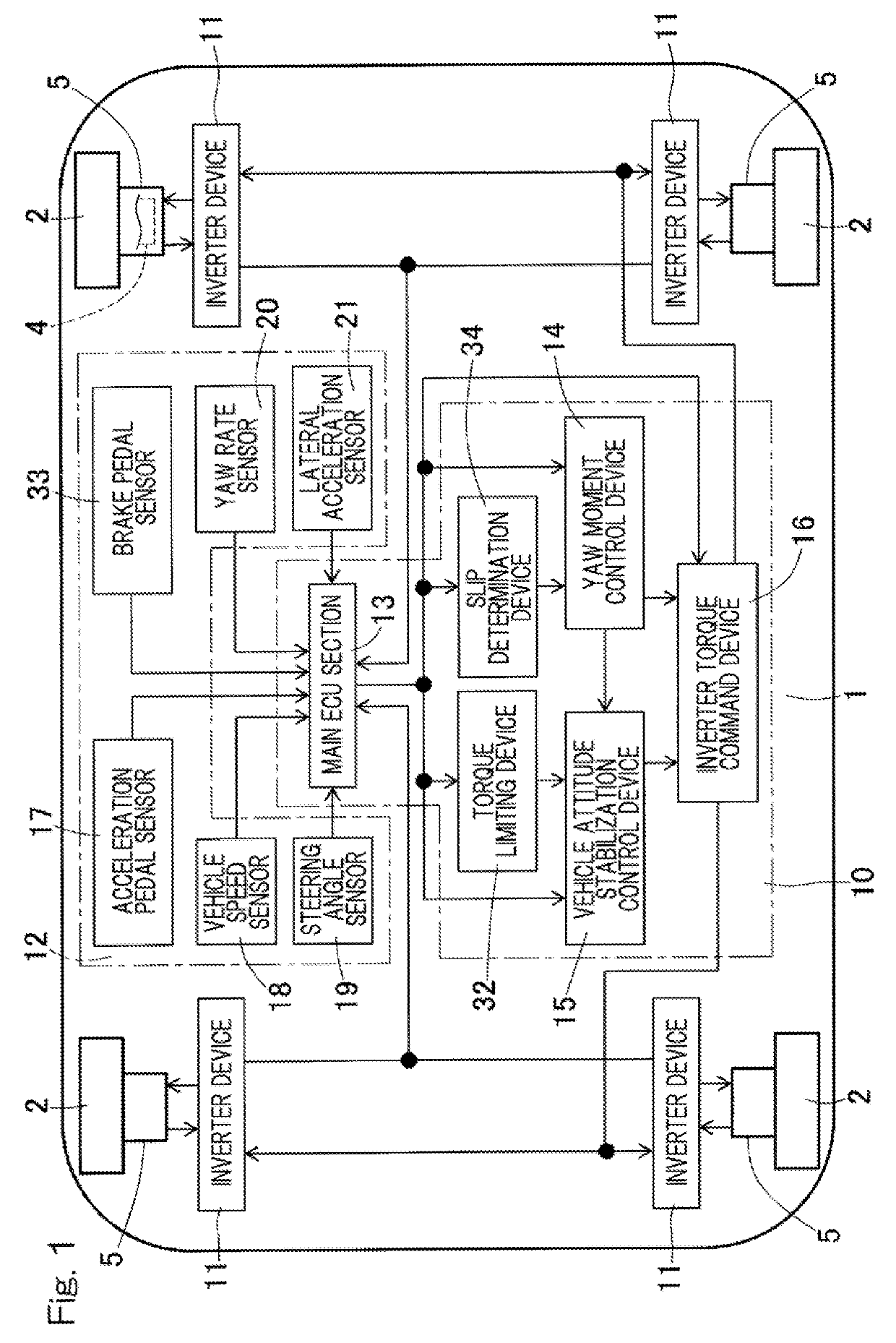
[0035]A vehicle turning control device according to one embodiment of the present invention will be described with reference to FIG. 1 to FIG. 12. As shown in FIG. 1, an example in which a vehicle 1 provided with the turning control device is of four-wheel independent driven type having in-wheel motor driving devices 5 for all the four wheels, will be described. In this vehicle 1, wheels 2 that are right and left rear wheels and wheels 2 that are right and left front wheels are independently driven by electric motors 4 each serving as a braking / driving source for generating a driving torque or a braking torque.

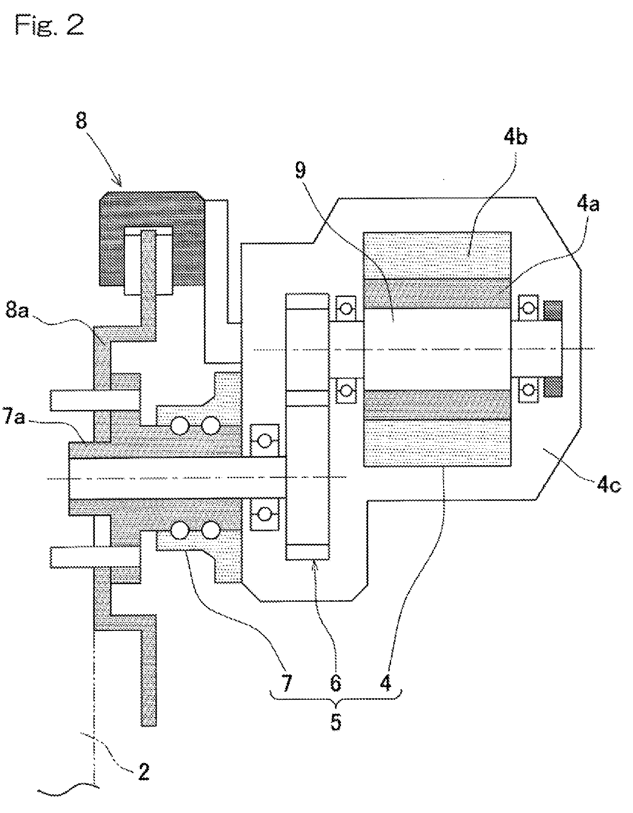
[0036]As shown in FIG. 2, each in-wheel motor driving device 5 has the electric motor 4, a speed reducer or reduction gear 6, and a wheel bearing 7, and these are partially or entirely provided in the wheel 2. Rotation of the electric motor 4 is transmitted to the wheel 2 via the speed reducer 6 and the wheel bearing 7. The in-wheel motor driving device 5 generates a driving t...


PUM


Abstract

This vehicle turning control device controls the turning characteristic of a vehicle having braking/driving sources capable of independently controlling a braking/driving torque for each wheel. The vehicle turning control device includes a yaw moment control device for controlling a yaw moment occurring in the vehicle, and a slip determination device for determining a road surface state from the angular velocity and the angular acceleration of the wheel and the vehicle speed. The yaw moment control device includes a control gain calculator for calculating a control gain, a target yaw rate calculator for calculating a target yaw rate from the vehicle speed, the steering angle, and the control gain, and a yaw moment calculator for calculating the braking/driving torque for each wheel in accordance with the target yaw rate. The control gain calculator calculates the control gain on the basis of a determination result of the slip determination device.

Description

CROSS REFERENCE TO THE RELATED APPLICATION[0001]This application is based on and claims Convention priority to Japanese patent application No. 2016-211425, filed Oct. 28, 2016, the entire disclosure of which is herein incorporated by reference as a part of this application.BACKGROUND OF THE INVENTIONField of the Invention[0002]The present invention relates to a vehicle turning control apparatus or device which optimally controls turning performance of a vehicle by causing a target yaw rate to approach the original response characteristic of the vehicle in accordance with slip of a wheel before saturation of a tire force.Description of Related Art[0003]Conventionally, technology is proposed in which a road surface frictional coefficient is estimated using an acceleration sensor and the like mounted on a vehicle, and yaw angular acceleration model following control (yaw moment control) or ESC (vehicle attitude stabilization control) is controlled in accordance with the road surface fr...

Claims


Application Information

Patent Timeline
IPC IPC(8): B60W30/045B60W40/064B60W40/068B60W40/114B60T8/172B60T8/1755
CPCB60W30/045B60W40/064B60W40/068B60W40/114B60T8/172B60T8/17551B60W2520/10B60W2540/18B60W2520/28B60W2550/148B60W2520/26B60W2720/14B60W2720/30B60W2050/0022B60W30/02Y02T10/72B60W2552/40B60L3/102B60L15/2072B60L2220/44B60L2240/22B60L2240/64B60L7/18B60L2260/28Y02T10/64Y02T90/16B60L9/18B60L15/20
Inventor SUZUKI, YUTA
Owner NTN CORP
Why Eureka
Try Eureka