Flexible ring fitting device

a flexible ring and fitting technology, applied in metal-working apparatus, vehicle components, metal-working apparatus, etc., can solve the problem of not easy to fit the o-ring into the workpiece groove, and achieve the effect of reducing the size, preventing excessive pressing force, and narrowing the movement range of the arm portion

Active Publication Date: 2019-08-15
HONDA MOTOR CO LTD
View PDF0 Cites 1 Cited by
  • Summary
  • Abstract
  • Description
  • Claims
  • Application Information

AI Technical Summary

Benefits of technology

[0011]A surface of the arm portion of the flexible ring assembly mechanism in contact with the flexible ring is inclined toward a tip. Accordingly, it is possible to press the flexible ring on the inclined surface in fitting the flexible ring into the annular groove of the workpiece by pressing the flexible ring with the arm portion. Accordingly, an excessive pressing force can be prevented from acting on the flexible ring from the arm portion either in a case where the diameter of the workpiece is large or in a case where the diameter of the workpiece is small. When the arm portion rotates, the flexible ring abuts against the inclined surface. Accordingly, the flexible ring can be smoothly guided to the annular groove of the workpiece. In a case where the flexible ring fitting device is further reduced in size, it is possible to narrow the movement range of the arm portion moved by the elastic body.
[0012]The flexible ring fitting device includes a pressing mechanism including a flexible ring holding mechanism (such as an O-ring holding shaft 426 to be described later) for fitting a part of the flexible ring into the annular groove of the workpiece. The pressing mechanism moves along with the flexible ring assembly mechanism. Accordingly, it is possible for the arm portion to push the other part of the flexible ring into the annular groove of the workpiece with the flexible ring partially fitted in the annular groove of the workpiece, and thus the other part of the flexible ring can be reliably fitted into the annular groove of the workpiece by the arm portion.
[0013]According to the present invention, it is possible to provide a flexible ring fitting device capable of fitting a flexible ring in response to workpieces having different diameters and capable of fitting the flexible ring even in the event of a positional relationship in which the axial center of rotation of an arm portion and the axial center of a workpiece are misaligned from each other.

Problems solved by technology

Besides, even in a case where O-rings are fitted with respect to the workpieces having one type of diameter by means of the devices according to the related art, it is not easy to fit the O-ring into the workpiece groove without a positional relationship in which the axial center of rotation of the arm portion and the axial center of the workpiece coincide with each other.

Method used


Image

  • Flexible ring fitting device
  • Flexible ring fitting device
  • Flexible ring fitting device

Examples


Embodiment Construction

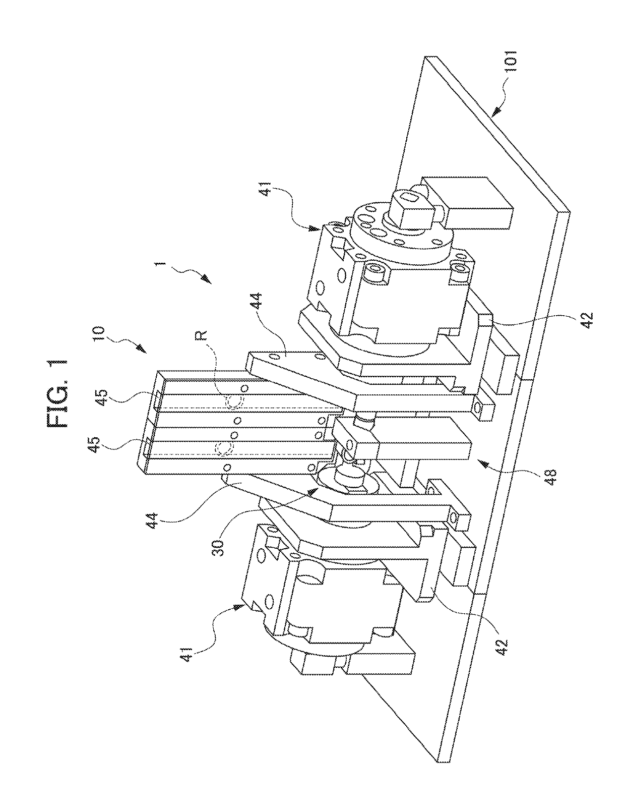
[0022]An embodiment of the present invention will be described in detail with reference to accompanying drawings. A flexible ring fitting device 1 is used so that a rubber-based O-ring R, which is a flexible ring, is fitted into a groove G (annular groove G). The groove G extends in the circumferential direction of a workpiece W and goes around. Each groove G is formed in the outer peripheral surface of a longitudinal end portion of the workpiece W. The workpiece W, which has a cylindrical shape, is a pipe member (pipe) interconnecting cases such as a crankcase and a differential case in a vehicle. FIG. 1 is a perspective view illustrating the flexible ring fitting device 1.

[0023]In the following description, the direction in which the rotary shafts of a pair of rotary cylinders 41 (described later) extend (substantially leftward-rightward direction in FIG. 1 in which the rotary cylinder 41 on the left side and the rotary cylinder 41 on the right side are interconnected in FIG. 1) i...


PUM


Abstract

The flexible ring fitting device includes a flexible ring disposition mechanism 10 for disposing a flexible ring R relative to an annular groove G of a workpiece W and flexible ring assembly mechanisms 421 and 422 including an arm portion 424 rotating while pushing the flexible ring R along the outer periphery of the workpiece W. The flexible ring assembly mechanisms 421 and 422 are movable with respect to the workpiece W and include an elastic body 51 urging the arm portion 424 of the flexible ring assembly mechanisms 421 and 422 so as to press the arm portion 424 with respect to the workpiece W.

Description

[0001]This application is based on and claims the benefit of priority from Japanese Patent Application No. 2018-023515, filed on 13 Feb. 2018, the content of which is incorporated herein by reference.BACKGROUND OF THE INVENTIONField of the Invention[0002]The present invention relates to a flexible ring fitting device.Related Art[0003]Known in the related art are devices fitting a flexible O-ring into a groove of a columnar workpiece that has an outer peripheral surface where the groove (annular groove) is formed (see, for example, Patent Documents 1 and 2). In the devices, a rod-shaped member rotating along the outer peripheral surface of the workpiece is rotated while the O-ring is pressed against the workpiece. The O-ring is fitted into the groove of the workpiece as a result.[0004]Patent Document 1: Japanese Examined Patent Application Publication No. H02-11384[0005]Patent Document 2: Japanese Unexamined Patent Application, Publication No. H11-114731SUMMARY OF THE INVENTION[0006]...

Claims


Application Information

Patent Timeline
Patent Type & Authority Applications(United States)
IPC IPC(8): B23P19/08
CPCB23P19/084B23P2700/50B25B27/02
Inventor FUKAZAWA, KINYA
Owner HONDA MOTOR CO LTD
Why Eureka
Try Eureka