Film forming method by sputtering and sputtering apparatus thereof

a sputtering apparatus and film forming technology, applied in the direction of cathode sputtering application, vacuum evaporation coating, coating, etc., can solve the problems of increasing hk and ms at the same time, and achieve good orientation characteristics, fine adjustment of film thickness distribution, and incident angle of substratum

Active Publication Date: 2010-06-03
CANON ANELVA CORP
View PDF6 Cites 20 Cited by
  • Summary
  • Abstract
  • Description
  • Claims
  • Application Information

AI Technical Summary

Benefits of technology

[0019]By rotating the target and / or stage concurrently with the sputtering treatment, it becomes possible to make the substrate incident angle large even in a narrow and limited space, and to form uniformly a film having good orientation characteristics. Further, the shield plate can rotate independently from the cathode and the stage, which is advantageous to finely adjust the distribution of film thickness and to enhance the selectivity for the incident angle of sputtered particles. Furthermore, the substrate placed on the substrate placing stage can rotate about two rotation axes, to enable an oriented film having high uniformity to be formed while further narrowing the moving range of the target and stage.

Problems solved by technology

Methods for increasing the resonant frequency include increasing the anisotropic magnetic field Hk or saturation magnetization Ms, but increasing Hk and Ms at the same time is generally difficult, and they are in a relation of trade-off.

Method used


Image

  • Film forming method by sputtering and sputtering apparatus thereof
  • Film forming method by sputtering and sputtering apparatus thereof
  • Film forming method by sputtering and sputtering apparatus thereof

Examples


Embodiment Construction

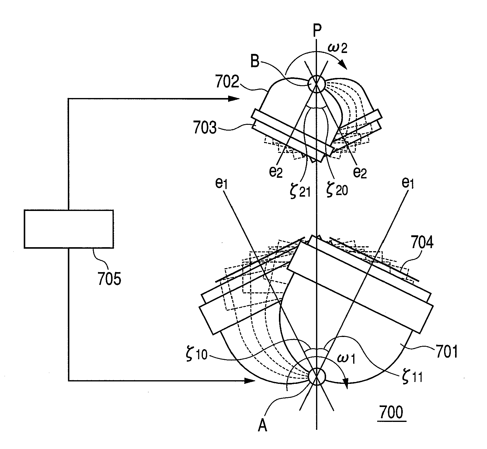
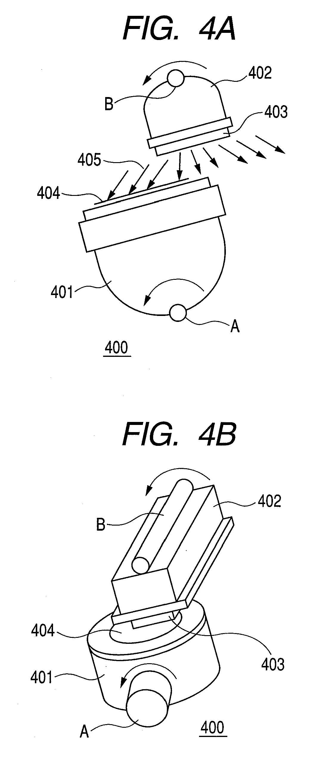
[0084]FIG. 4A is a side view of a first sputtering apparatus 400 according to the present invention. FIG. 4B is a perspective view of the first sputtering apparatus 400 according to the present invention. The sputtering apparatus 400 includes a stage 401 for placing a substrate 404, and a cathode 402 for supporting a target 403, wherein a target supporting surface of the cathode 402 and a substrate supporting surface of the stage 401 are arranged so as to face to each other. The stage 401 and the cathode 402 are provided with a rotation axis A and a rotation axis B, respectively, and the stage 401 and the cathode 402 are constituted so as to rotate about the rotation axis A and the rotation axis B, respectively, at an arbitrary angle. For example, the stage 401 and the cathode 402 may be rotated using such a rotation means as a motor, and the rotation means may be controlled by a control device. The rotation axis A and the rotation axis B are arranged in parallel with each other, an...


PUM

PropertyMeasurementUnit
thickness distributionaaaaaaaaaa
angleaaaaaaaaaa
distanceaaaaaaaaaa

Abstract

To provide a sputtering apparatus that enables oblique film forming by arranging a target and a substrate so as to allow sputtered particles emitted from the target to obliquely enter the substrate selectively, and can form a magnetic film having high uniaxial magnetic anisotropy uniformly and compactly. A sputtering apparatus includes a cathode having a sputtering target supporting surface, the cathode being provided with a rotation axis about which the sputtering target supporting surface rotates, and a stage having a substrate supporting surface, the stage being provided with a rotation axis about which the substrate supporting surface rotates, and the sputtering apparatus is constituted such that the sputtering target supporting surface and the substrate supporting surface face to each other, and are rotatable independently about respective rotation axes. Further, it is constituted such that a shield plate is arranged between the sputtering target supporting surface and the substrate supporting surface, and is rotatable independently from the cathode and the stage.

Description

CROSS-REFERENCES TO RELATED APPLICATIONS[0001]This application is a continuation application of International Application No. PCT / JP2007 / 066750, filed on Aug. 29, 2007, the entire contents of which are incorporated by reference herein.BACKGROUND OF THE INVENTION[0002]1. Field of the Invention[0003]The present invention relates to a film forming method by sputtering and a sputtering apparatus thereof.[0004]2. Related Background Art[0005]In these years, high frequency wave applications of an magnetic element have been enlarged in read / write heads, microinductors and micro transformer and the like, and a magnetic thin film having good high-frequency characteristics in a GHz band is needed. Accordingly, research and development relating to these are actively carried out. In order to use a magnetic thin film in a high-frequency band, it is necessary to increase an electrical resistance of the thin film, thereby reducing an eddy-current loss, and increasing a resonant frequency. Methods f...

Claims


Application Information

Patent Timeline
Patent Type & Authority Applications(United States)
IPC IPC(8): C23C14/36
CPCC23C14/044C23C14/225C23C14/3407C23C14/505C23C14/548H01J37/3455H01J37/34H01J37/3405H01J37/3414H01J37/3435H01F41/18
Inventor ENDO, TETSUYAABARRA, EINSTEIN NOEL
Owner CANON ANELVA CORP
Why Eureka
Try Eureka