Driving cylinder of a pile driving rig and a pile driving rig

Active Publication Date: 2019-08-15
JUNTTAN OY
View PDF0 Cites 0 Cited by
  • Summary
  • Abstract
  • Description
  • Claims
  • Application Information

AI Technical Summary

Benefits of technology

The invention simplifies and improves the driving cylinder of a pile driving rig. It uses a simpler and more durable solenoid valve, reducing the number of parts and manufacturing costs. Additionally, it uses a stroke damping mounting that reduces the loads on the hammer body and minimizes noise.

Problems solved by technology

The disadvantage of these currently known driving cylinder solutions is that the implementation of the solenoid valve closing and opening the pressure medium ducts between the cylinder chambers and leading away from the chambers is complex, requires a considerable number of gaskets due to the several joints and is, therefore, laborious to service and repair.

Method used


Image

  • Driving cylinder of a pile driving rig and a pile driving rig
  • Driving cylinder of a pile driving rig and a pile driving rig
  • Driving cylinder of a pile driving rig and a pile driving rig

Examples


Embodiment Construction

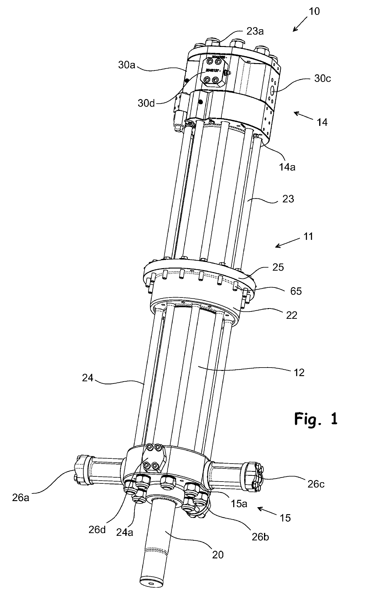
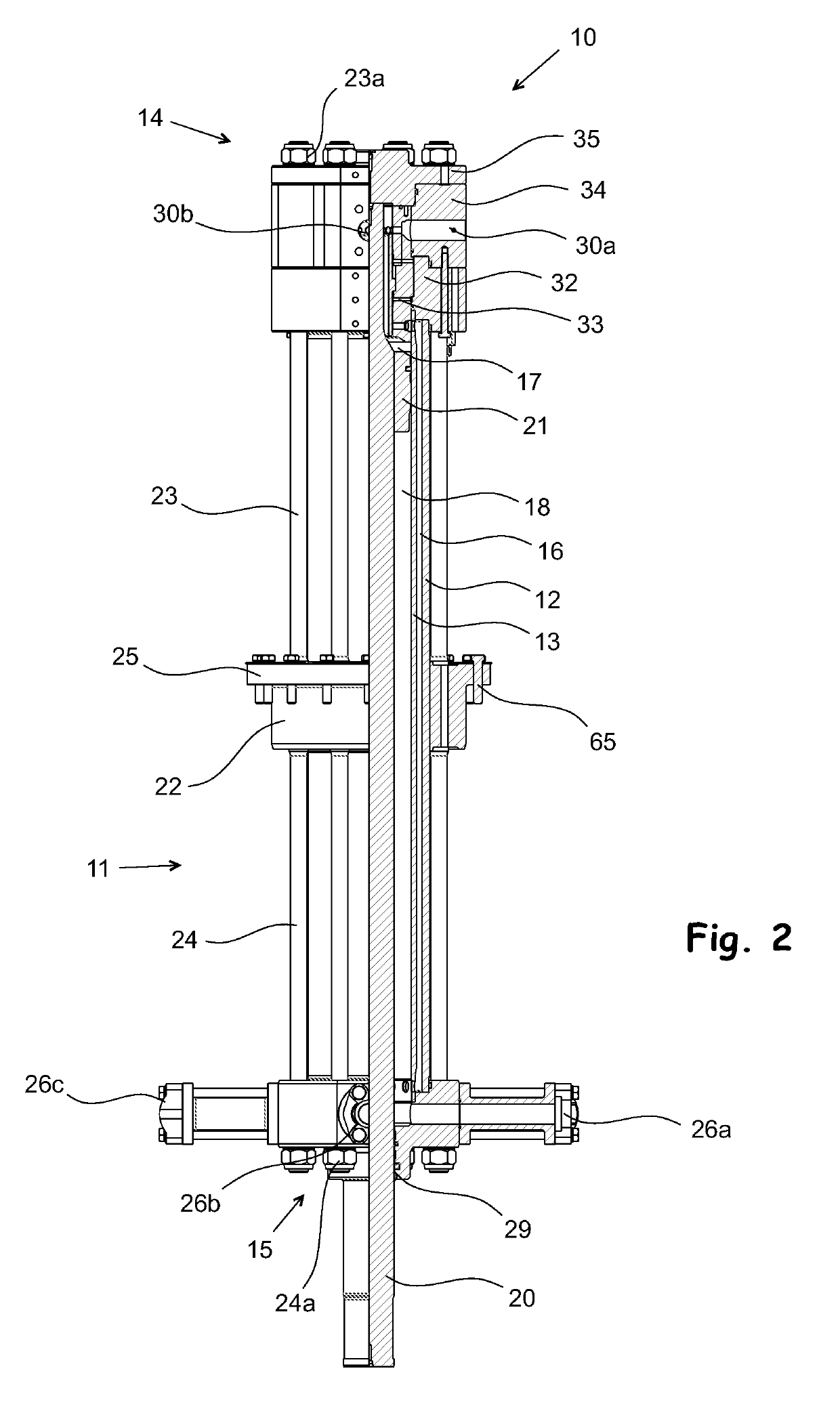
[0033]The hydraulic driving cylinder 10 shown in FIGS. 1-10 is located in the upper part of the hammer in a pile driving rig, inside it, in the manner shown in FIG. 10, in such a way that it can be used to reciprocate the ram block 60 (shown in FIG. 9) located in the lower part of the hammer during the driving of the pile into the ground. The moving end of the driving cylinder 10, that is, the piston rod 20, is fastened by means of a fixture 50 (shown in FIG. 9) at its end to a fastening point in the upper part of the ram block. The driving cylinder is a double-acting differential cylinder, that is, the movement of the end moving in it is based on the fact that the force generated by the pressure medium at the moving end is greater above (i.e. in the piston-side chamber 17) the driving cylinder 10 moving inside the driving cylinder when the piston moves downwards, and greater below the piston (in the piston rod side cylinder chamber) when the piston moves upwards. This type of hydra...


PUM


Abstract

A driving cylinder of a pile driving rig includes a solenoid valve for controlling an operation of the driving cylinder, which solenoid valve, is a slide valve, which is located at least partly at a piston-side head of the driving cylinder, and a stem of the slide valve is at least partly outside an inner cylinder liner in a direction of motion of a piston part. Further disclosed is a pile driving rig comprising the driving cylinder according to the invention.

Description

FIELD OF THE INVENTION[0001]The object of the invention is a driving cylinder of a pile driving rig and a pile driving rig.BACKGROUND OF THE INVENTION[0002]A driving cylinder is a hydraulic actuator located inside the hammer of a hydraulic pile driving rig, the purpose of the driving cylinder being reciprocate the ram block impacting the driven pile during the driving of the pile into the ground. In currently known hydraulic pile driving rigs, the driving cylinder is usually a double-acting differential hydraulic cylinder, in which the piston rod side cylinder chamber is connected to the piston-side cylinder chamber, most typically by means of a hydraulic hose, or in such a way that the cylinder part is comprised of two cylinder liners within each other, in which case the pressure medium may be conveyed from one cylinder chamber to another through the empty space left between the cylinder liners fitted within each other. By means of this arrangement, the movement of the moving end o...

Claims


Application Information

Patent Timeline
IPC IPC(8): E02D7/10
CPCE02D7/10E02D7/14B25D9/18E02D2250/00E02D7/00
Inventor HALONEN, ANTTI
Owner JUNTTAN OY
Why Eureka
Try Eureka