Fresnel lens

a lens and lens technology, applied in the field of lenses, can solve the problems of reducing clarity, deteriorating imaging quality, and reducing the optical imaging quality of normal fresnel lenses, and achieve the effect of fine optical imaging quality

Active Publication Date: 2019-08-15
GENIUS ELECTRONICS OPTICAL CO LTD
View PDF4 Cites 2 Cited by
  • Summary
  • Abstract
  • Description
  • Claims
  • Application Information

AI Technical Summary

Benefits of technology

[0004]The disclosure provides a Fresnel

Problems solved by technology

According to the related art, the optical imaging quality of normal Fresnel lenses are often deteriorated because of lens flares or light spots on images, which often results from stray light generated by reflections of refractions by light rays incident

Method used


Image

  • Fresnel lens
  • Fresnel lens
  • Fresnel lens

Examples


Embodiment Construction

[0010]The Fresnel lens provided in the following embodiments is applicable to optical imaging lenses or optical lenses for illumination in head-mounted display apparatus capable of simulating three-dimensional visual perception (e.g., virtual reality, VR) or in portable electronic apparatuses including mobile phones, cameras, tablet PCs, personal digital assistants (PDA), and so on.

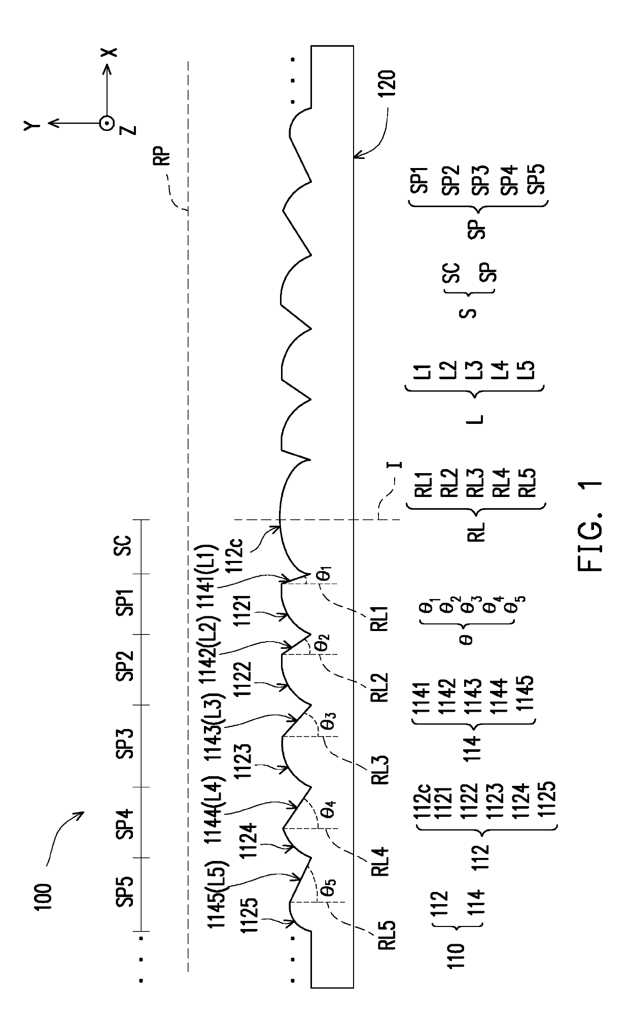
[0011]To elaborate the arrangement of the Fresnel lens, the Fresnel lens provided in the following embodiments may be considered as being located within a three-dimensional space constructed by x-axis, y-axis, and z-axis, and every two of the x-axis, y-axis, and z-axis are perpendicular to each other.

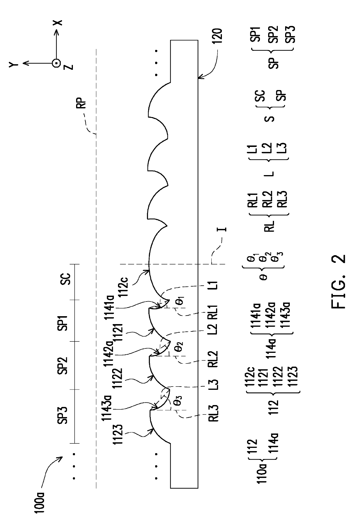
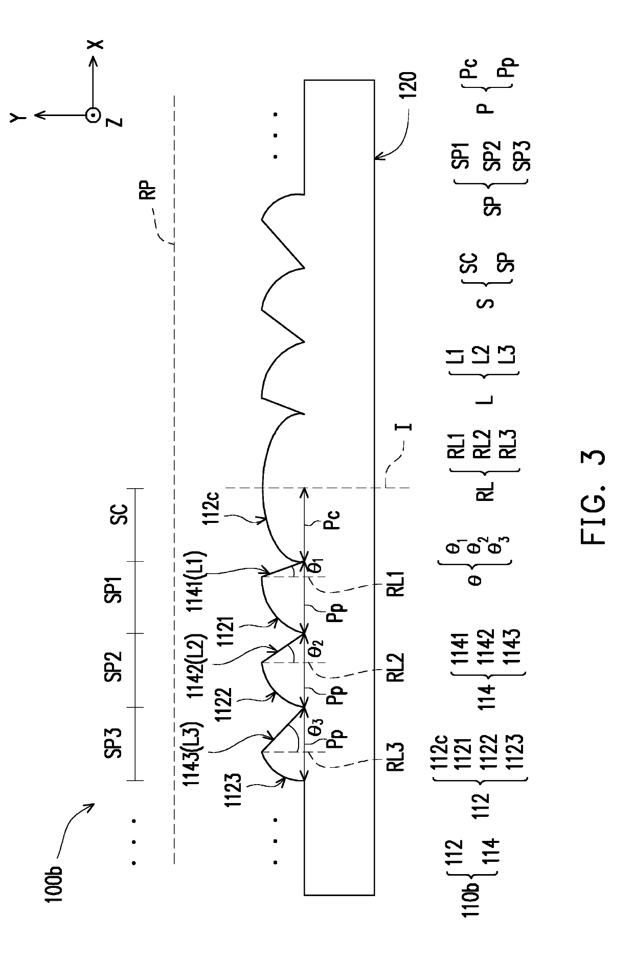
[0012]FIG. 1 to FIG. 4 are schematic cross-sectional views of a Fresnel lens according to different embodiments of the invention.

[0013]With reference to FIG. 1, in the present embodiment, the Fresnel lens 100 has a Fresnel surface 110 and a surface 120 opposite to the Fresnel surface 110. According to an embo...


PUM


Abstract

A Fresnel lens includes a Fresnel surface that includes effective Fresnel surfaces allowing imaging rays to pass through. Two adjacent effective Fresnel surfaces are connected through a non-effective Fresnel surface. On a cross-section including an optical axis of the Fresnel lens, a draft angle is between a reference line and a connecting straight line between one end of each non-effective Fresnel surface located at a tooth peak of the Fresnel lens and the other end of each non-effective Fresnel surface located at a tooth valley of the Fresnel lens. The optical axis coincides with the cross-section. The reference line is parallel to the optical axis and passes through the end of the effective Fresnel surface located at the tooth peak of the Fresnel lens. The draft angles each smaller than 90 degrees include first, second, third, fourth, and fifth draft angles which gradually increase radially outward from the optical axis.

Description

CROSS-REFERENCE TO RELATED APPLICATION[0001]This application claims the priority benefit of Chinese application serial no. 201810144667.7, filed on Feb. 12, 2018. The entirety of the above-mentioned patent application is hereby incorporated by reference herein and made a part of this specification.TECHNICAL FIELD[0002]The disclosure relates to a lens; more particularly, the disclosure relates to a Fresnel lens.DESCRIPTION OF RELATED ART[0003]According to the related art, the optical imaging quality of normal Fresnel lenses are often deteriorated because of lens flares or light spots on images, which often results from stray light generated by reflections of refractions by light rays incident on non-effective Fresnel surfaces. Practically, when the Fresnel lenses are formed by injection molding, draft angles are often required for separating the Fresnel lenses and the molds. In the related art, however, each draft angle of a Fresnel lens stays the same; hence, the light rays incident...

Claims


Application Information

Patent Timeline
IPC IPC(8): G02B3/08
CPCG02B3/08
Inventor LIN, YI-JYUNCHEN, EN-CHIEH
Owner GENIUS ELECTRONICS OPTICAL CO LTD
Why Eureka
Try Eureka