
Lens

a technology of lenses and lenses, applied in the field of lenses, can solve the problems of direct affecting the optical imaging quality, difficult to reduce the cost and volume of the lens to an ideal value, and difficult to give consideration to both, so as to improve the optical quality and reduce the stray light

Active Publication Date: 2020-08-06
RAYS OPTICS
View PDF0 Cites 2 Cited by
  • Summary
  • Abstract
  • Description
  • Claims
  • Application Information

AI Technical Summary

Benefits of technology

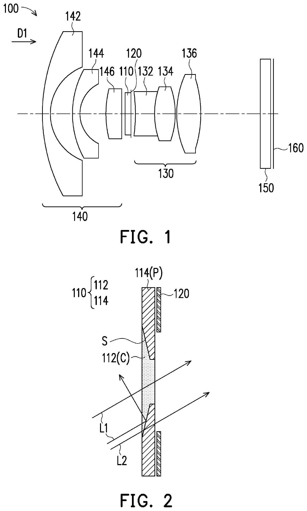
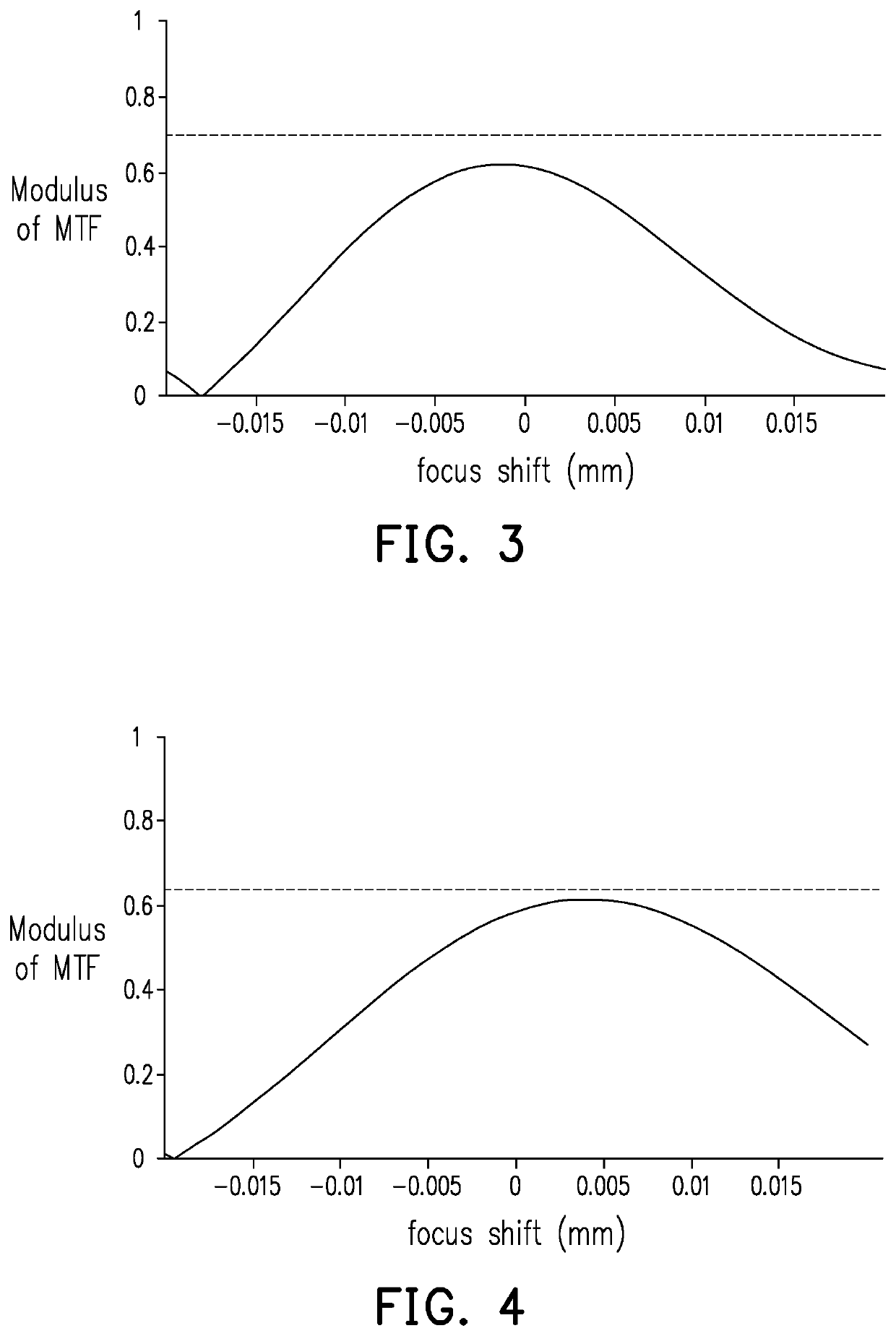
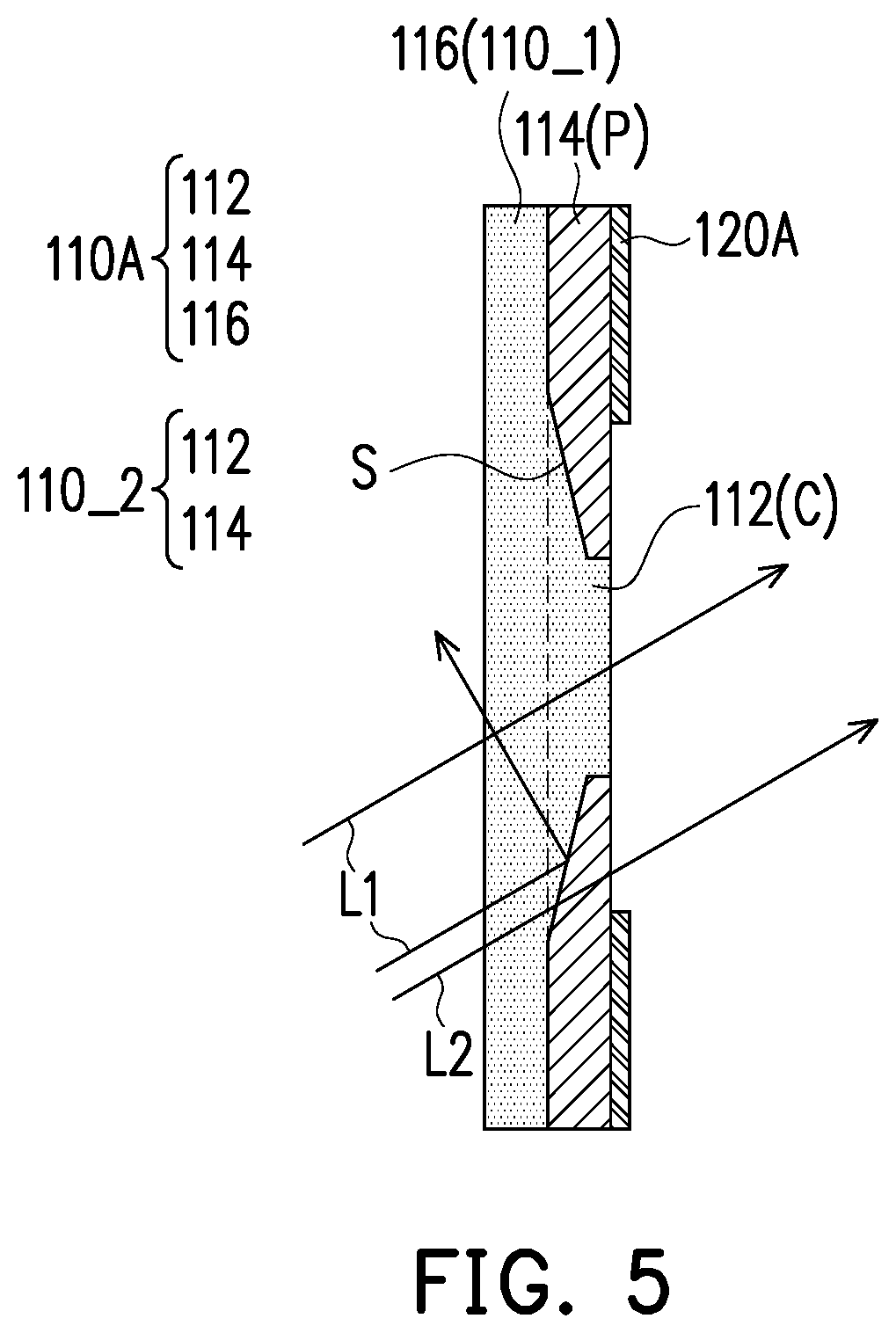
The patent describes a lens with a special filter structure that allows the lens to have different openings for different wavelengths of light. This improves the optical quality by reducing stray light. The lens has a central region that allows visible light and infrared light to pass through, and a peripheral region that can reflect the visible light. The design generates different aperture values for the visible and infrared light, without the need for an infrared filter during the day and night. The lens also has a tapered shape that prevents reflecting the visible light to the minified side of the lens, resulting in improved optical imaging quality and reduced stray light.

Problems solved by technology

Therefore, under the demand of both, most of the lenses strike the balance between the two as product specifications, and it is difficult to give consideration to both.
However, due to the presence of movable parts, it will be difficult to reduce the cost and volume of the lens to an ideal value.
Moreover, when the image-taking lens takes images, stray light are generated, which directly affects the optical imaging quality.
In addition, according to the related art, since the position and the value of the aperture are fixed, as to the optical design, the best focus point of the visible light and the infrared light along the optical axis can only be achieved by relying on the correction of special glass material, and it is difficult to achieve full day-night confocal imaging.
However, either way leads to the increase in the manufacturing cost.

Method used


Image

  • Lens
  • Lens
  • Lens

Examples


Embodiment Construction

[0015]FIG. 1 is a schematic view of a lens according to an embodiment of the disclosure. Please refer to FIG. 1. In the present embodiment, a lens 100 including a filter 110, an aperture stop 120, and a lens set 130 sequentially arranged along a first direction D1 is provided. Particularly, the lens 100 can further include another lens set 140 located in front of the filter 10 and including a glass cover 150 and an imaging plane 160. The lens 100 provided in the present embodiment can be applied in an image capturing apparatus (e.g., a camera or a camcorder) as an imaging lens, so as to capture light transmitted along the first direction D1 and form images on the imaging plane 160. Alternatively, in other embodiments, the lens 100 can serve as a projection lens and can be applied to an image projecting device, e.g., a projector or the like, so as to transmit an image light along a direction opposite to the first direction D1 and form an image on an external projection target (not sh...


PUM


Abstract

A lens including a filter, an aperture stop, and a lens set sequentially arranged along a first direction is provided. The filter includes a central region and a peripheral region. The central region has a first light transmission band for a wavelength range of a visible light and a second light transmission band for a wavelength range of an infrared light. The peripheral region surrounds the central region. The peripheral region has a third light transmission band for the wavelength range of the infrared light and is substantially opaque to the visible light, and an area of one portion of the central region surrounded by the peripheral region is tapered toward the first direction.

Description

CROSS-REFERENCE TO RELATED APPLICATION[0001]This application claims the priority benefit of Taiwan application no. 108104240, filed on Feb. 1, 2019. The entirety of the above-mentioned patent application is hereby incorporated by reference herein and made a part of this specification.BACKGROUNDTechnical Field[0002]The disclosure generally relates to a lens. More particularly, the disclosure relates to a lens having different F-number (hereinafter called as aperture values) for light having different wavelengths.Description of Related Art[0003]In the existing image-taking lens design, when the lens is used to take pictures at low illumination at night, the desired small aperture value ranges from 1.0 to 1.8; in the daytime, high resolution is preferred, and the desired large aperture value ranges from 2.2 to 3.0. Therefore, under the demand of both, most of the lenses strike the balance between the two as product specifications, and it is difficult to give consideration to both. In o...

Claims


Application Information

Patent Timeline
IPC IPC(8): G02B5/20G02B9/62G02B13/14G02B7/00G03B17/12
CPCG02B13/14G02B5/208G02B9/62G03B17/12G02B7/006G02B5/005G02B13/04
Inventor LEE, CHEN-CHENGTSAI, CHEN-YIWANG, SHIN-JENHUNG, KUO-HSIANGLIN, CHIH-LINGLIN, MENG-WEILU, YU-CHIA
Owner RAYS OPTICS
Learn More