Image splicing method, apparatus, terminal, and storage medium

a splicing method and image technology, applied in the field of image processing technologies, can solve the problems of undesirable image splicing effect, and achieve the effect of improving the image splicing

Active Publication Date: 2019-08-15
TENCENT TECH (SHENZHEN) CO LTD
View PDF0 Cites 17 Cited by
  • Summary
  • Abstract
  • Description
  • Claims
  • Application Information

AI Technical Summary

Benefits of technology

[0009]The technical solutions provided in the embodiments of this application have the following beneficial effects. The partially overlapped region is selected from the initial spliced image obtained through projection according to the primary position parameter. The partial position parameter of the partial image region corresponding to the partially overlapped region in the current image is calculated, and the current image is projected to the projection canvas again according to the partial position parameter and the primary position parameter, to obtain the target spliced image. The technical solutions can resolve a problem that when a terminal obtains an initial spliced image by pro

Problems solved by technology

Because the primary position parameter may be inapplicable to the entire image, an overlapped region of the initial spliced image obtained by the terminal cannot achieve desirable effect and an image splicing effect is undesirable.
The technical solutions can resolve a problem that when a terminal obtains an initial splice

Method used


Image

  • Image splicing method, apparatus, terminal, and storage medium
  • Image splicing method, apparatus, terminal, and storage medium
  • Image splicing method, apparatus, terminal, and storage medium

Examples


Embodiment Construction

[0024]Exemplary embodiments are described herein in detail and examples hereof are shown in the accompanying drawings. When the following descriptions relate to the accompanying drawings, the same numbers in different accompanying drawings indicate the same or similar elements unless otherwise indicated. Implementations described in the following exemplary embodiments do not indicate all implementations consistent with this application. On the contrary, the implementations are only examples of the apparatus and the method described in the appended claims in detail consistent with some aspects of this application.

[0025]Several terms in this specification are first described.

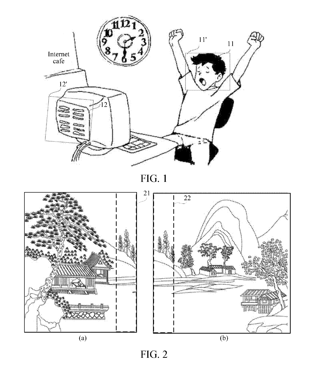
[0026]A depth plane is a plane in which an object in an image is located in an actual setting. For example, in an image shown in FIG. 1, a plane in which the head 11 of a person is located is a depth plane 11′, and a plane in which the back 12 of a computer is located is a depth plane 12′. Generally, in an image, ...


PUM


Abstract

Embodiments of this application disclose an image splicing method and apparatus, a terminal, and a storage medium thereof. The image splicing method includes determining a primary position parameter of a current image according to a first overlapped region in the current image; and projecting the current image to a projection canvas according to the primary position parameter to obtain an initial spliced image, the initial spliced image being obtained by splicing the current image and the neighboring image. The method further includes selecting a partially overlapped region from a second overlapped region of the initial spliced image; calculating a partial position parameter of a partial image region corresponding to the partially overlapped region in the current image; and projecting the current image to the projection canvas again according to the primary position parameter and the partial position parameter, to obtain a target spliced image.

Description

RELATED APPLICATIONS[0001]This application claims priority to PCT Application No. PCT / CN2018 / 078275, filed on Mar. 7, 2018, which in turn claims priority to Chinese Patent Application No. 201710176990.8, entitled “IMAGE SPLICING METHOD AND APPARATUS” filed with China National Intellectual Property Administration on Mar. 22, 2017. The two applications are incorporated by reference in their entirety.FIELD OF TECHNOLOGY[0002]Embodiments of this application relate to the field of image processing technologies, and in particular, to an image splicing method and apparatus, a terminal, and a storage medium.BACKGROUND OF THE DISCLOSURE[0003]Image splicing technologies are widely applied in technical areas such as panoramic photo shooting, space probing, remote sensing image processing, and medical image analysis. Image splicing technology refers to the technology in which two or more than two partially overlapped images are spliced seamlessly, to compose a large-frame or wide-viewing-angle ...

Claims


Application Information

Patent Timeline
IPC IPC(8): G06T3/40G06T7/11G06T7/593G06T7/13G06K9/46G06V10/44
CPCG06T3/4038G06T7/11G06T7/593G06T7/13G06K9/46G06V10/44
Inventor YUAN, ZIJINJIAN, WEIHUA
Owner TENCENT TECH (SHENZHEN) CO LTD
Why Eureka
Try Eureka