Stator arrangement for an axial-flow machine

a technology of axial flow and axial flow, which is applied in the direction of windings, magnetic circuits characterised by magnetic materials, and magnetic circuit shapes/forms/construction, etc., and can solve problems such as the need for considerable time and/or mechanical complexity

Active Publication Date: 2019-08-15
MIBA SINTER AUSTRIA
View PDF10 Cites 10 Cited by
  • Summary
  • Abstract
  • Description
  • Claims
  • Application Information

AI Technical Summary

Benefits of technology

[0046]For all above-mentioned embodiments, it is also conceivable that the stator arrangement is formed substantially symmetrically in axial direction, whereby the use of two ro

Problems solved by technology

For realization of known stator arrangements having a multiplicity of stator teeth having stator

Method used


Image

  • Stator arrangement for an axial-flow machine
  • Stator arrangement for an axial-flow machine
  • Stator arrangement for an axial-flow machine

Examples


Embodiment Construction

[0059]By way of introduction, it is pointed out that like parts in the differently described embodiments are denoted with like reference symbols or like structural part designations, wherein the disclosures contained in the entire description can be carried over logically to like parts with like reference symbols or like structural-part designations. The position indications chosen in the description, such as top, bottom, side, etc., for example, are also relative to the figure being directly described as well as illustrated, and these position indications are to be logically carried over to the new position upon a position change.

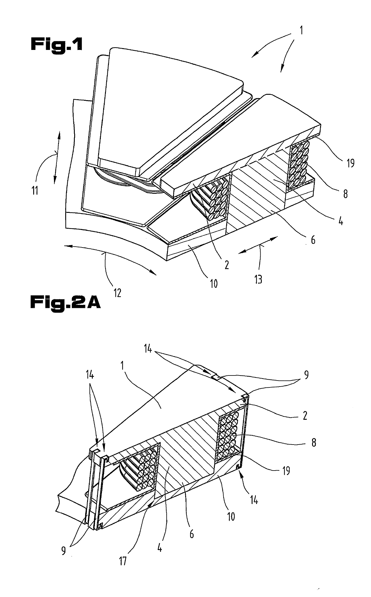
[0060]In FIG. 1, a sectional diagram is shown through a partial portion of an exemplary stator arrangement. The stator teeth 1 illustrated here have end portions situated oppositely in axial direction 11, i.e. one tooth tip 2 and one tooth root 6, between which a tooth core 4 extends that is wound with a coil winding 8.

[0061]At its root cross-sectional are...


PUM


Abstract

A stator arrangement for an axial-flow machine includes a stator having stator teeth circumferentially distributed concentrically and axially separated from a rotor by an air gap. The stator teeth have two axially-opposite end portions and a tooth core therebetween. Each tooth core is wound with at least one coil winding. The first end portion facing the rotor forms a tooth tip having a tip cross-sectional area larger than the core cross-sectional area. The second end portion, turned away from the rotor, forms a tooth root, having a root cross-sectional area, which is joined to a reflux plate. The tooth tip of each stator tooth as well as the reflux plate respectively has at least one recess for at least one tooth securing device, and each stator tooth is securely joined by the at least one tooth securing device to the reflex plate in at least axial direction.

Description

CROSS REFERENCE TO RELATED APPLICATIONS[0001]Applicant claims priority under 35 U.S.C. § 119 of Austrian Application No. A 50128 / 2018 filed Feb. 9, 2018, the disclosure of which is incorporated by reference.BACKGROUND OF THE INVENTION1. Field of the Invention[0002]The invention relates to a stator arrangement for an axial-flow machine, as well as to an axial-flow machine having such a stator arrangement.2. Description of the Related Art[0003]Electric machines with disk-like rotor and stator disposed parallel thereto are known from the prior art and find use, for example, in axial-flow machines. Usually, the rotor has a multiplicity of permanent magnets, which rotate past oppositely situated, electromagnetically excitable poles of the stator in a manner separated by an air gap. These electromagnetically excitable poles are formed, for example, as stator teeth from a soft-magnetic material, around the tooth core of which a coil winding induces a magnetic field upon passage of current....

Claims


Application Information

Patent Timeline
IPC IPC(8): H02K1/18H02K3/50
CPCH02K1/182H02K3/50H02K1/02H02K1/148H02K5/15H02K2203/12H02K1/146H02K5/04H02K21/24H02K3/522
Inventor STETINA, GEROLDSANDNER, CHRISTIANRIEDL, THOMASANDESSNER, DIETMAR
Owner MIBA SINTER AUSTRIA
Why Eureka
Try Eureka