

Bone conduction headset
a conduction headset and headset body technology, applied in the direction of diaphragm construction, coupling device connection, loudspeaker, etc., can solve the problem of difficulty in keeping conversations with adjacent partners, and achieve the effect of easy operation, easy collection of vocal cord vibration, and simple operation
- Summary
- Abstract
- Description
- Claims
- Application Information
AI Technical Summary
Benefits of technology
Problems solved by technology
Method used
Image

Examples
first exemplary embodiment
[0030]Hereinafter, a first exemplary embodiment will be described with reference to FIGS. 1 to 5.
[1-1. Overall Configuration of Communication Device]
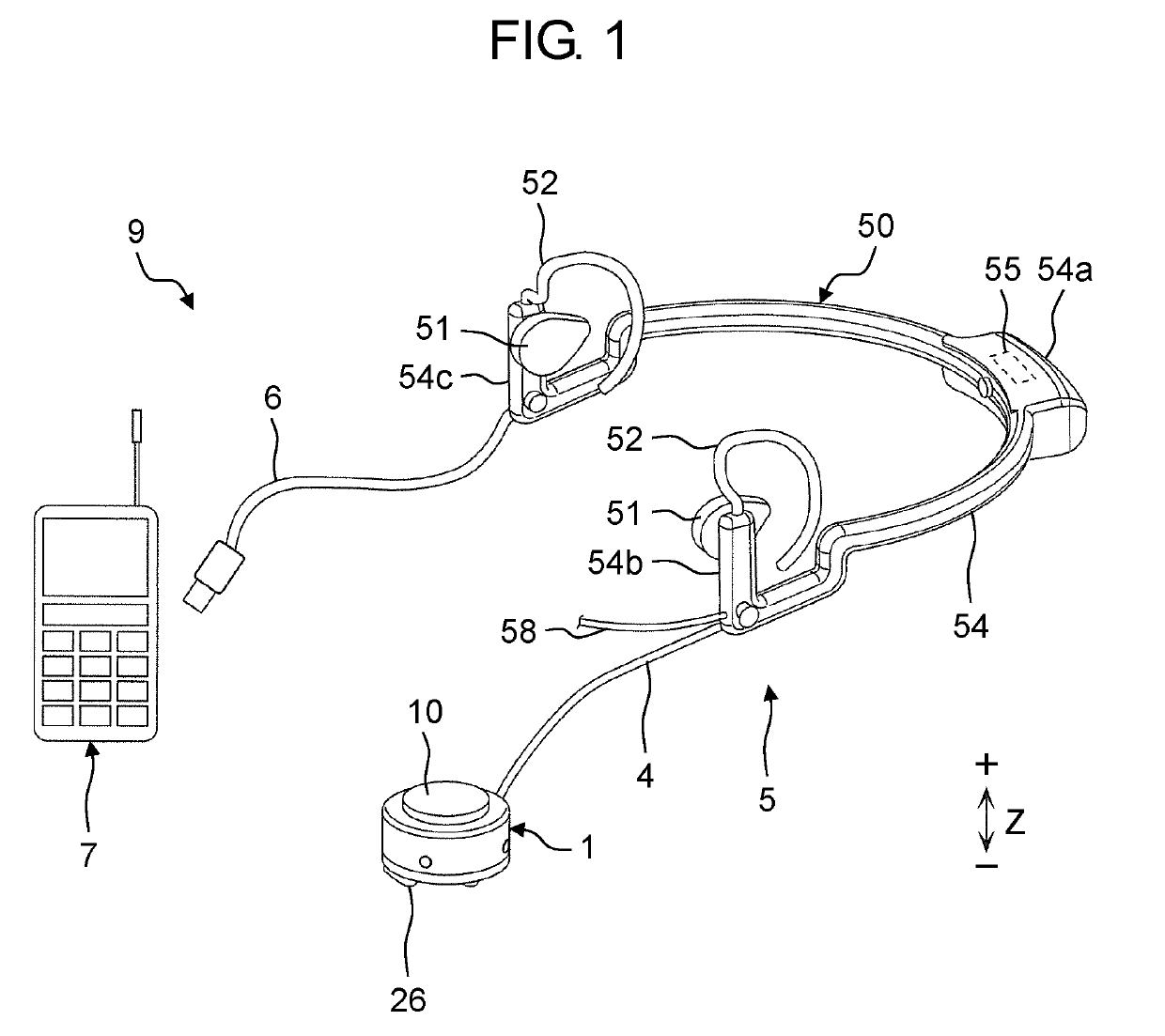
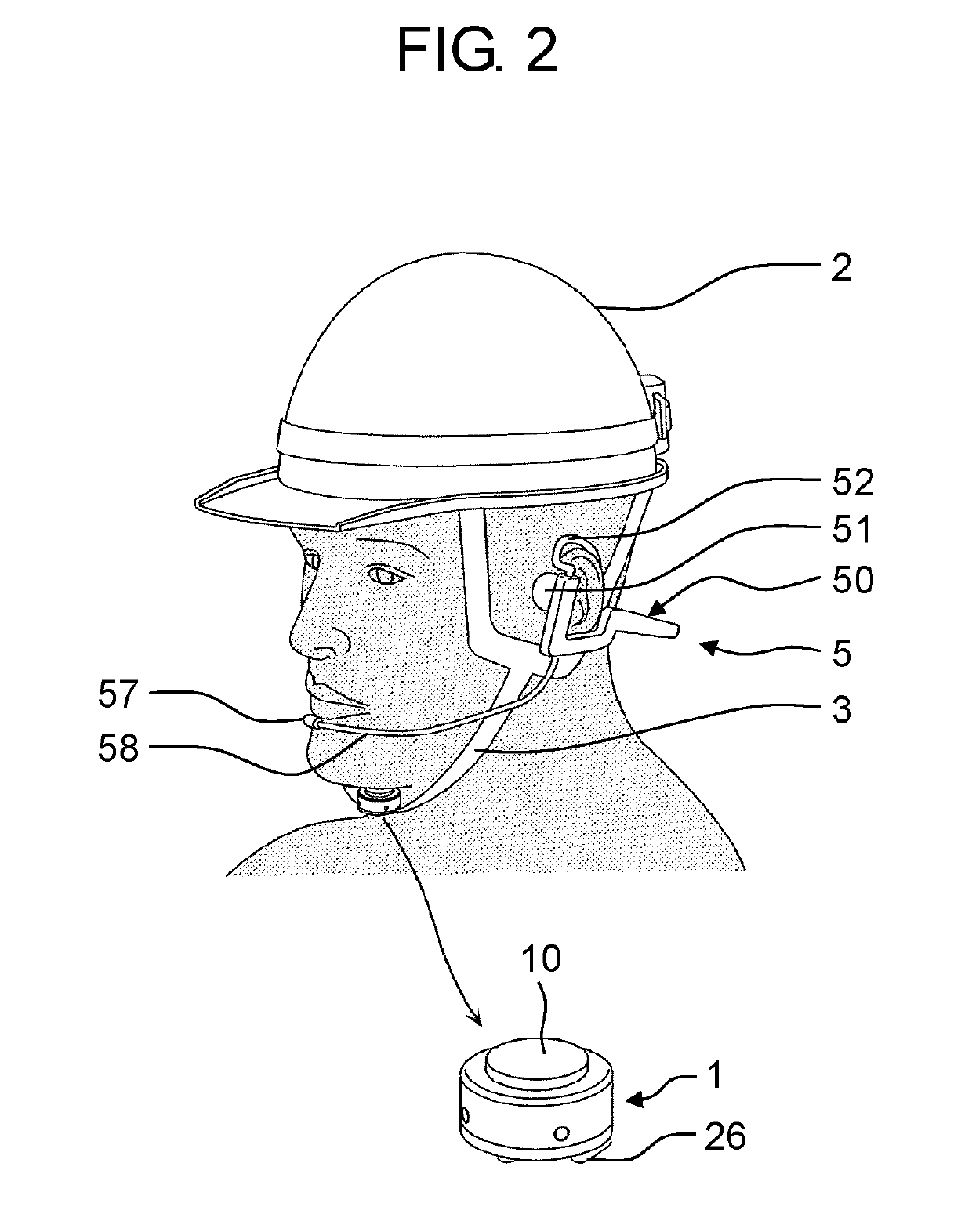
[0031]FIG. 1 is a perspective view illustrating communication device 9 including bone conduction headset 5, according to the first exemplary embodiment. FIG. 2 is a view illustrating an aspect of use of bone conduction headset 5 including bone conduction microphone 1.
[0032]As illustrated in FIG. 1, communication device 9 includes bone conduction headset 5 including bone conduction microphone 1 and headset main body 50, and transceiver 7. Bone conduction microphone 1 is coupled to headset main body 50 via microphone cable 4. Headset main body 50 includes ear hooks 52. Ear hooks 52 are to be hooked to ears of a human body. Headset main body 50 is thus worn on a head. Headset main body 50 is coupled to transceiver 7 via headset cable 6. Transceiver 7 is attached to a part of a garment, and is configured to perform communications with an ex...
second exemplary embodiment
[0085]Bone conduction headset 5A and communication device 9A according to a second exemplary embodiment will be described below with reference to FIGS. 6 to 10.
[2-1. Overall Configuration of Communication Device]
[0086]FIG. 6 is a perspective view illustrating communication device 9A including bone conduction headset 5A. FIG. 7 is a perspective view of bone conduction headset 5A, when viewed differently in angle from FIG. 6. FIG. 8 is a perspective view illustrating an aspect of use of bone conduction headset 5A.
[0087]As illustrated in FIGS. 6 and 7, communication device 9A includes bone conduction headset 5A including sound microphone 57 and headset main body 50, and transceiver 7. Sound microphone 57 is coupled to headset main body 50 via microphone holder 58. Headset main body 50 includes a pair of speakers 51 and a pair of ear hooks 52. Ear hooks 52 are to be hooked to ears of a human body. Headset main body 50 is thus worn on a head. Speakers 51 are wire-coupled to transceiver 7...
modification examples
[2-4. Modification Examples]
[0121]In the second exemplary embodiment, one of the ends of support member 54, i.e., end 54b, is coupled with sound microphone 57 via microphone holder 58, as well as is coupled with bone conduction microphone 1 via microphone cable 4.
[0122]Here is described, as modification examples to the second exemplary embodiment, cases where bone conduction microphone 1 and sound microphone 57 are detachably and replaceably coupled to headset main body 50.
[0123]First, a connection part including connector 170 is provided to end 54b of headset main body 50. Connector 180 is used at an end of microphone cable 4, which is to be coupled to bone conduction microphone 1, i.e., to be coupled to headset main body 50. Connector 190 is used at an end of microphone holder 58 to be coupled to sound microphone 57, i.e., to be coupled to bone conduction headset 5A. With this configuration, bone conduction microphone 1 and sound microphone 57 are detachable and replaceable with r...
PUM
 Abstract
Description
Claims
Application Information