Caseless rearview mirror assembly

a rearview mirror and assembly technology, applied in the field of rearview mirror assemblies for vehicles, can solve the problems of unattractive size, heavy mirror housing/casing, and impaired vibration performan

Active Publication Date: 2019-08-22
MAGNA MIRRORS OF AMERICA INC
View PDF0 Cites 23 Cited by
  • Summary
  • Abstract
  • Description
  • Claims
  • Application Information

AI Technical Summary

Benefits of technology

[0006]In accordance with an aspect of the present invention, a caseless mirror assembly comprises a caseless electro-optic rearview mirror reflective element that includes a front transparent glass substrate with a rounded outer circumferential glass edge and a rear substrate with a rounded outer circumferential edge, with an electro-optic medium sandwiched between the front transparent glass substrate and the rear substrate. A plate (including a pivot element for pivotally mounting the mirror assembly at an interior portion of the vehicle) is part of or attached at the rear substrate. The caseless mirror assembly of the present invention thus provides a low profile mirror head. Control circuitry for automatically controlling dimming of the electro-optic medium is disposed separate from the caseless electro-optic rearview mirror reflective element, and the control circuitry may control dimming of the electro-optic medium of the caseless electro-optic rearview mirror reflective element via wiring that passes through the ball and socket pivot joint.

Problems solved by technology

Conventional interior rearview mirrors thus utilize a bulky and often heavy mirror housing / casing with disadvantages that include impaired vibration performance due to weight, bulky and thus unattractive size, and manufacturing cost and complexity challenges.

Method used


Image

  • Caseless rearview mirror assembly
  • Caseless rearview mirror assembly
  • Caseless rearview mirror assembly

Examples


Embodiment Construction

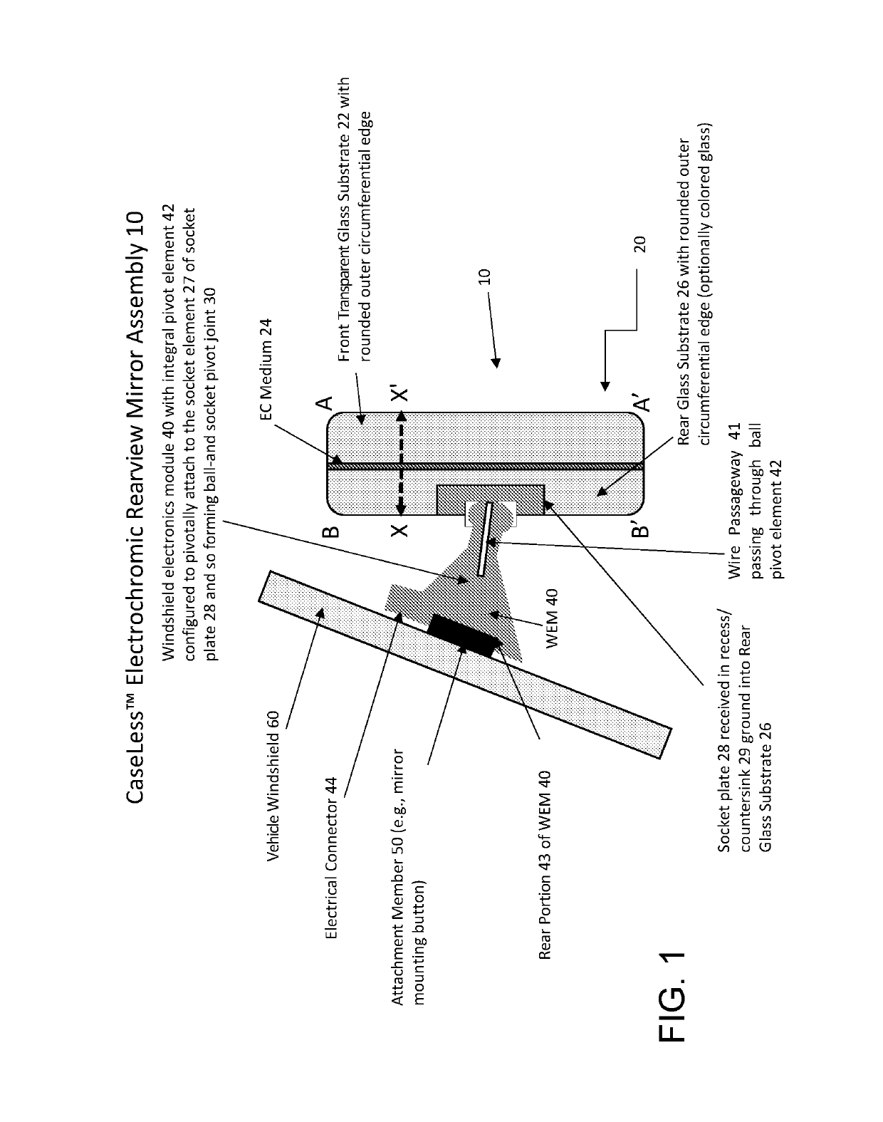
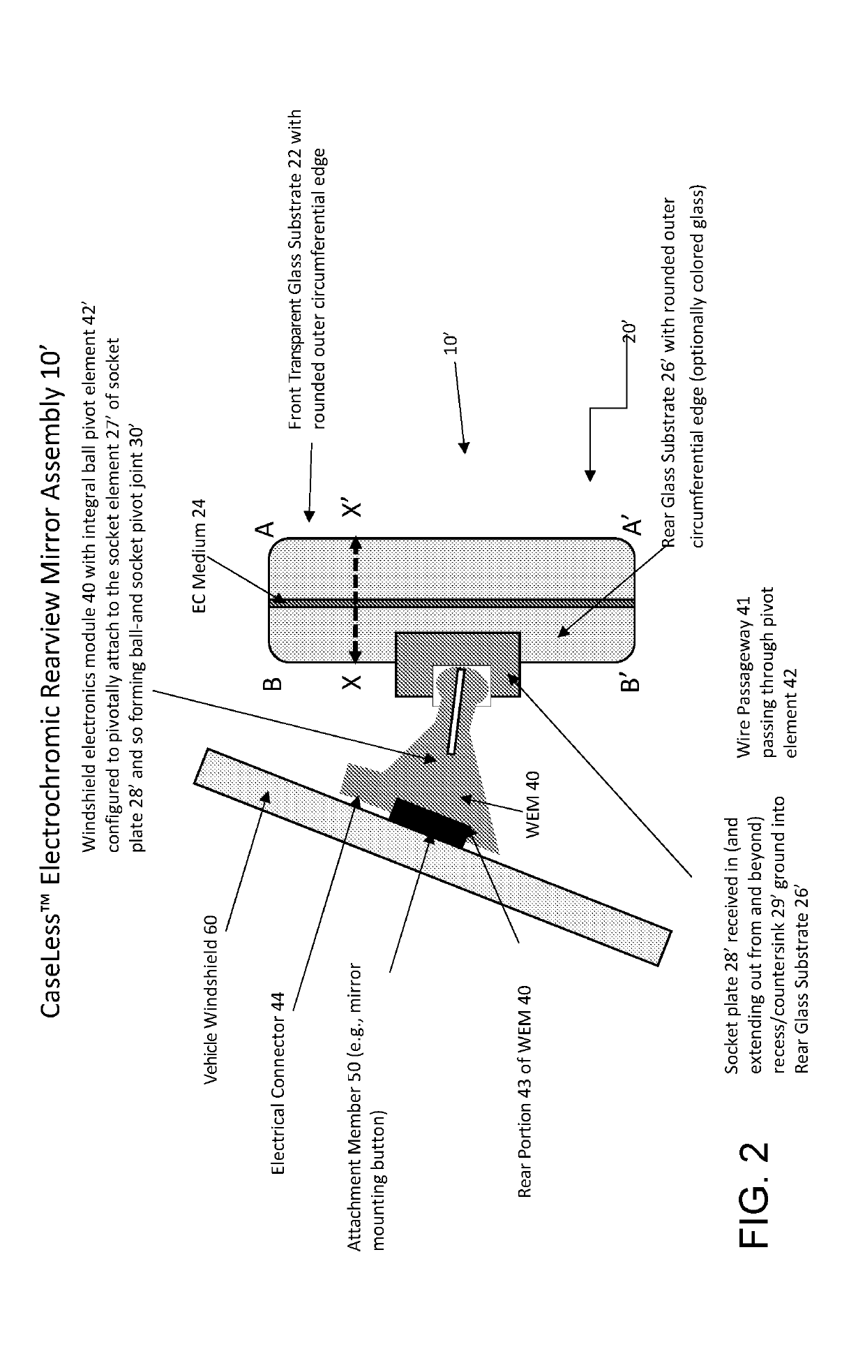
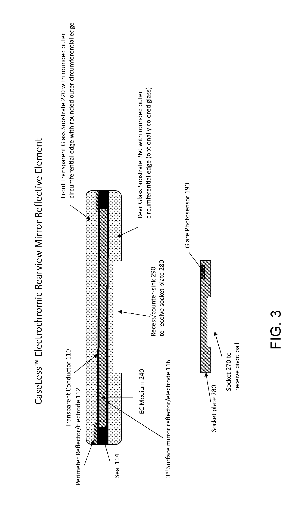
[0043]FIG. 1 shows an embodiment of an interior electrochromic rearview mirror assembly 10 that does not have a mirror case in accordance with the present invention. Caseless interior electrochromic rearview mirror assembly 10 comprises interior electrochromic rearview mirror reflective element 20 that pivots (via ball-and-socket pivot joint 30) about windshield electronics module (WEM) 40 that is adapted for attaching to (and demounting from) attachment member 50 that is bonded by adhesive to the inner surface of windshield 60. Interior electrochromic rearview mirror reflective element 20 comprises a front transparent glass substrate 22 and a rear glass substrate 26 that sandwich an electrically-dimmable electrochromic (EC) medium 24. Examples of suitable EC media to use are disclosed in U.S. Pat. Nos. 6,420,036; 5,724,187 and 5,688,663; 5,128,799; 5,073,012; 5,115,346; 5,140,455; 5,142,407; 5,151,816; 5,239,405; 5,500,760 and 5,424,865, which are hereby incorporated herein by refe...


PUM

PropertyMeasurementUnit
radiusaaaaaaaaaa
thicknessaaaaaaaaaa
thicknessaaaaaaaaaa

Abstract

An electro-optic rearview mirror assembly for a vehicle includes a caseless electro-optic rearview mirror reflective element and a plate attached at the rear of the reflective element. The mirror reflective element connected to and pivotal about a windshield electronics module via a ball and socket pivot joint. Control circuitry may be disposed in a windshield electronics module for automatically controlling dimming of the electro-optic medium or alternatively, dimming of the electro-optic medium is automatically controlled via a multifunctional rear backup camera system of the equipped vehicle. Optionally, the control circuitry controls dimming of the electro-optic medium of the mirror reflective element via wiring that passes through the ball and socket pivot joint. Optionally, image data captured by the multifunctional rear backup camera may be used for ambient light determination and to provide video image display at the interior rearview mirror assembly.

Description

CROSS REFERENCE TO RELATED APPLICATIONS[0001]The present application claims the filing benefits of U.S. provisional applications, Ser. No. 62 / 471,491, filed Mar. 15, 2017, Ser. No. 62 / 371,256, filed Aug. 5, 2016, Ser. No. 62 / 344,527, filed Jun. 2, 2016, Ser. No. 62 / 340,679, filed May 24, 2016, Ser. No. 62 / 338,124, filed May 18, 2016, and Ser. No. 62 / 330,556, filed May 2, 2016, which are hereby incorporated herein by reference in their entireties.FIELD OF THE INVENTION[0002]The present invention relates to rearview mirror assemblies for vehicles and, more particularly, to interior rearview mirror assemblies adjustably mounted at an interior of a vehicle.BACKGROUND OF THE INVENTION[0003]Rearview mirrors have been used in the interior of vehicles for decades upon decades. Conventionally, an interior rearview mirror assembly comprises a mirror reflective element housed or encased by or in a casing or housing and includes a mounting portion that attaches typically at the inner surface of...

Claims


Application Information

Patent Timeline
Patent Type & Authority Applications(United States)
IPC IPC(8): G02F1/163B60R1/04G02F1/155G02F1/161B60R1/08
CPCG02F1/163B60R1/04B60R1/088G02F1/161G02F1/155G02F1/153
Inventor LYNAM, NIALL R.HABIBI, HAMIDBLANK, RODNEY K.KOETJE, CHRISTOPHER R.LARSON, MARK L.FOLEY, IV, PATRICK M.GALLAS, MICHAEL L.
Owner MAGNA MIRRORS OF AMERICA INC
Why Eureka
Try Eureka