Hand-held device

a handheld device and handheld technology, applied in the direction of magnetic bodies, electrical apparatus casings/cabinets/drawers, manufacturing tools, etc., can solve the problems of metal chips sticking to the casing of the operation device therefrom, prone to scratching, etc., and achieve the effect of suppressing the adhesion of metal chips

Active Publication Date: 2019-08-29
FANUC LTD
View PDF0 Cites 1 Cited by
  • Summary
  • Abstract
  • Description
  • Claims
  • Application Information

AI Technical Summary

Benefits of technology

The patent text is about a handheld device that prevents metal chips from sticking to it. This is achieved by a design where the device has a moving unit that surrounds the magnet, which prevents the metal chips from being attracted to the device and getting stuck to it. This design prevents damage caused by metal chips and improves the device's performance.

Problems solved by technology

However, metal chips such as metal pieces and metal powder generated during the machining of the machine tool or the like may stick to the casing of the operation device by the magnetic force of the magnet, and when the device with the metal chips sticking thereto is attached to the metal board, the metal board is liable to be scratched.
Further, the task of removing metal chips sticking to the casing of the operation device therefrom tends to be troublesome.

Method used


Image

  • Hand-held device
  • Hand-held device
  • Hand-held device

Examples


modification 1

[Modification 1]

[0041]FIG. 6 is a perspective view showing a moving unit 26 of modification 1. In FIG. 6, though part of the moving unit 26 is cut away for convenience of explanation, it is not actually cut off. The moving unit 26 of the modification 1 is different from the moving unit 16 having the sliding part 20 and the urging element 22 in that it is a bellows member. The moving unit 26 is made of a nonmetallic material such as a resin and incorporates a magnet 14.

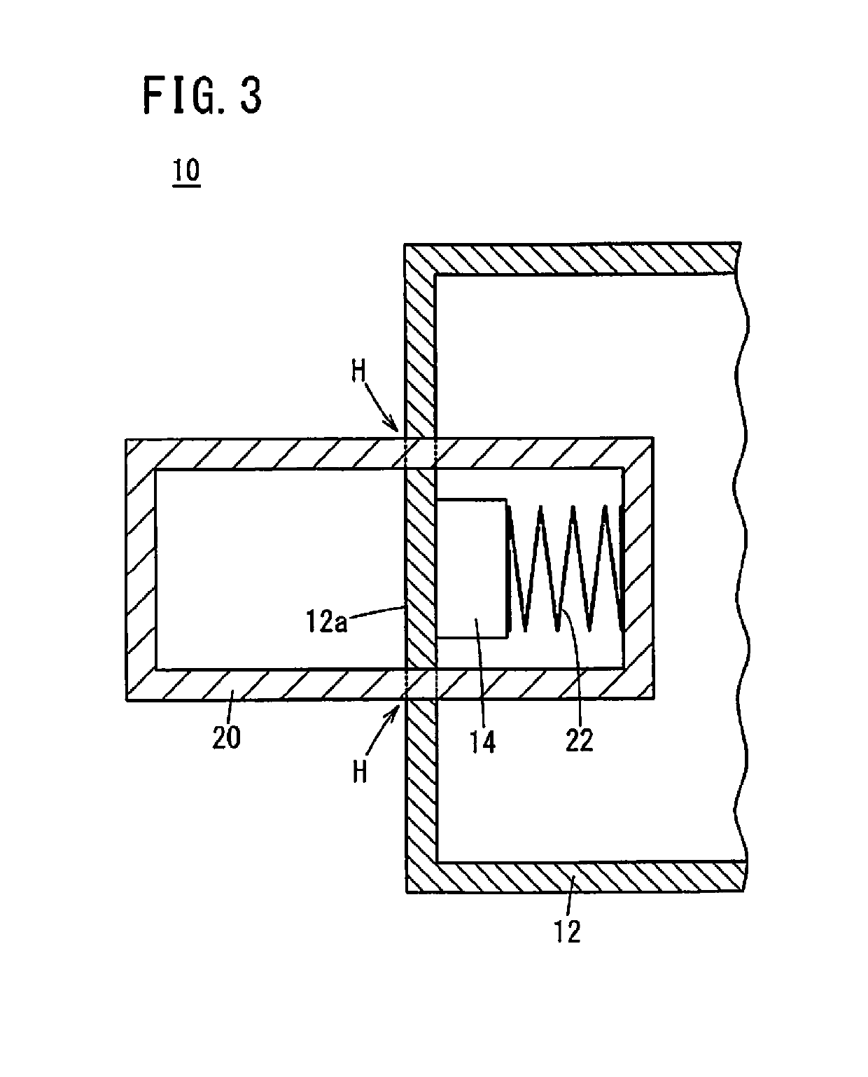
[0042]FIG. 7 is a sectional view showing a hand-held device 10 including the moving unit 26 of the modification 1, viewed from the same viewpoint as in FIG. 3. FIG. 8 is a sectional view of the hand-held device 10 including the moving unit 26 of the modification 1, viewed from the same viewpoint as in FIG. 4. The moving unit 26 is arranged on the attachment face 12a side of the casing 12.

[0043]Specifically, the moving unit 26 is arranged in a depressed portion 12c formed on the attachment face 12a side of the casing 12...

modification 2

[Modification 2]

[0048]FIG. 9 is a sectional view showing a hand-held device 10 of modification 2, viewed from the same viewpoint as in FIG. 4. The hand-held device 10 of the modification 2 is different from the above embodiment in that it has a depressed portion 12c on the attachment face 12a side of the casing 12, whereas the hand-held device 10 of the above embodiment has no depressed portion 12c.

[0049]The sliding part 20 is arranged so as to penetrate the bottom portion of the depressed portion 12c, and is slidable in the penetrating direction while surrounding the magnet 14. Thus, similarly to the above modification 1, in the attached state where the casing 12 is attached to the metal board MB, the distal end portion 16a of the moving unit 16 (the sliding part 20) is accommodated in the depressed portion 12c. Therefore, no gap is formed between the casing 12 and the metal board MB, so that the casing 12 can be stably attracted to the metal board MB.

modification 3

[Modification 3]

[0050]Though, in the above-described embodiment, the hand-held device 10 is an operation device for operating a machine tool, it may be an operation device for operating a machine, an appliance and the like other than machine tools. Further, the hand-held device 10 may be an electronic device not including operation keys K, or may be an appliance that does not include any electronic component. In short, the hand-held device 10 may be any device as long as it is of a portable type that can be attached to and detached from the metal board MB.

[0051][Modification 4]

[0052]The above embodiment and modifications 1 to 3 may be arbitrarily combined as long as no inconsistency occurs.

[Technical Ideas] Technical ideas that can be grasped from the above embodiment and modifications are described below.

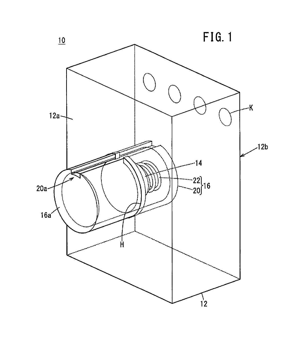
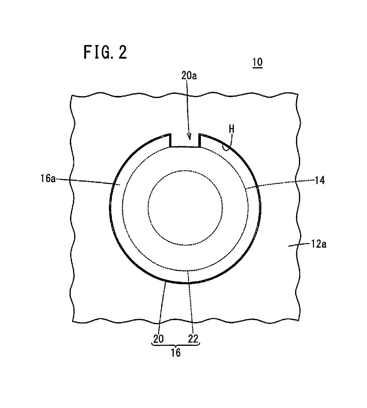
[0053]The hand-held device (10) is a portable device configured to be attached to and detached from a metal board (MB), and includes a casing (12) and a magnet (14) disposed in the...


PUM

PropertyMeasurementUnit
Forceaaaaaaaaaa

Abstract

A hand-held device is a portable device configured to be attached to and detached from a metal board, and includes a casing and a magnet disposed in the casing. The hand-held device further includes a moving unit disposed so as to surround the magnet when an attachment face of the casing that is attached to the metal board is viewed from the front, the moving unit being configured to move so as to extend in a direction in which a distal end portion of the moving unit moves away from the attachment face of the casing when the casing is detached from the metal board.

Description

CROSS-REFERENCE TO RELATED APPLICATION[0001]This application is based upon and claims the benefit of priority from Japanese Patent Application No. 2018-030916 filed on Feb. 23, 2018, the contents of which are incorporated herein by reference.BACKGROUND OF THE INVENTIONField of the Invention[0002]The present invention relates to a portable hand-held device that is attachable to and detachable from a metal board.Description of the Related Art[0003]As a portable hand-held device, for example, an operation device such as a remote controller can be mentioned, and a magnet is used to make such an operation device attachable to and detachable from a metal board. For example, Japanese Laid-Open Patent Publication No. 2011-001718 discloses a detachable structure for a remote controller that performs remote control. This structure uses a magnet to allow the remote controller to be detachably fixed to a wall by the magnetic force of the magnet.SUMMARY OF THE INVENTION[0004]Meanwhile, in factor...

Claims


Application Information

Patent Timeline
IPC IPC(8): B23H1/00B25H3/04
CPCB25H3/04B23H1/00B23Q1/0045B23Q11/00B23H11/00H01F7/0252H05K5/0204
Inventor OOTSUKA, YUUMAOKAMURA, HIDEKI
Owner FANUC LTD
Why Eureka
Try Eureka