Joining device and method for joining strips to form a tire component

a technology which is applied in the field of joining device and tire component for joining strip to form tire component, can solve the problems of inability to tolerate the accumulation of tolerance between the discharge conveyor and the gripper that retains the second strip, deformation of subsequent tire layers, and inability to meet the requirements of the application

Active Publication Date: 2019-09-05
VMI HOLLAND BV
View PDF1 Cites 0 Cited by
  • Summary
  • Abstract
  • Description
  • Claims
  • Application Information

AI Technical Summary

Benefits of technology

[0009]Preferably, the deflection member is biased to move into the deflection position, wherein the deflection member is movable against the bias in a retraction direction opposite to the deflection direction into a flush position in which the deflection member lies flush or substantially flush with the retaining plane. Unlike with a rigidly mounted or actively driven deflection member, the biased deflection member allows for the deflection member to move back when sufficient pressure has been applied to press the leading end against the support member. Hence, the leading end is not unnecessarily deformed or compressed between the deflection member and the support member.
[0010]Alternatively, the joining device comprises a deflection actuator that is operationally coupled to the deflection member for actively driving the movement of the deflection member in the deflection direction. The deflection actuator allows for accurate control of the position of the deflection member.

Problems solved by technology

However, tolerances buildup between the discharge conveyor and the gripper that retains the second strip is inevitable.
With some strips being only a few tenths of a millimeter in height, such tolerance buildup is unacceptable.
Said protruding edge may cause deformations in subsequent tire layers that are to be applied to said surface.

Method used


Image

  • Joining device and method for joining strips to form a tire component
  • Joining device and method for joining strips to form a tire component
  • Joining device and method for joining strips to form a tire component

Examples


first embodiment

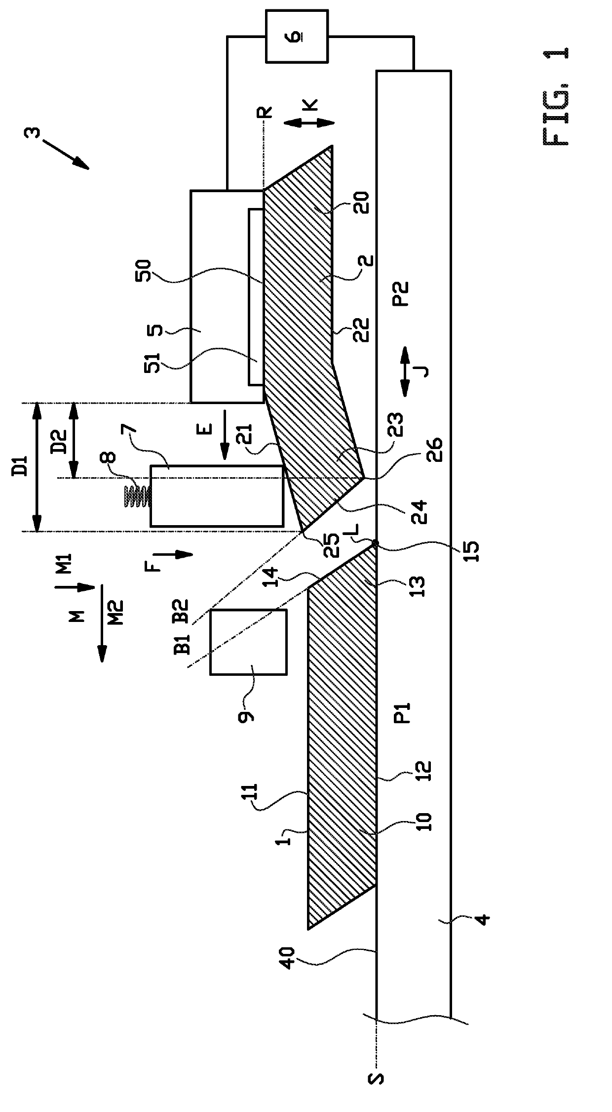
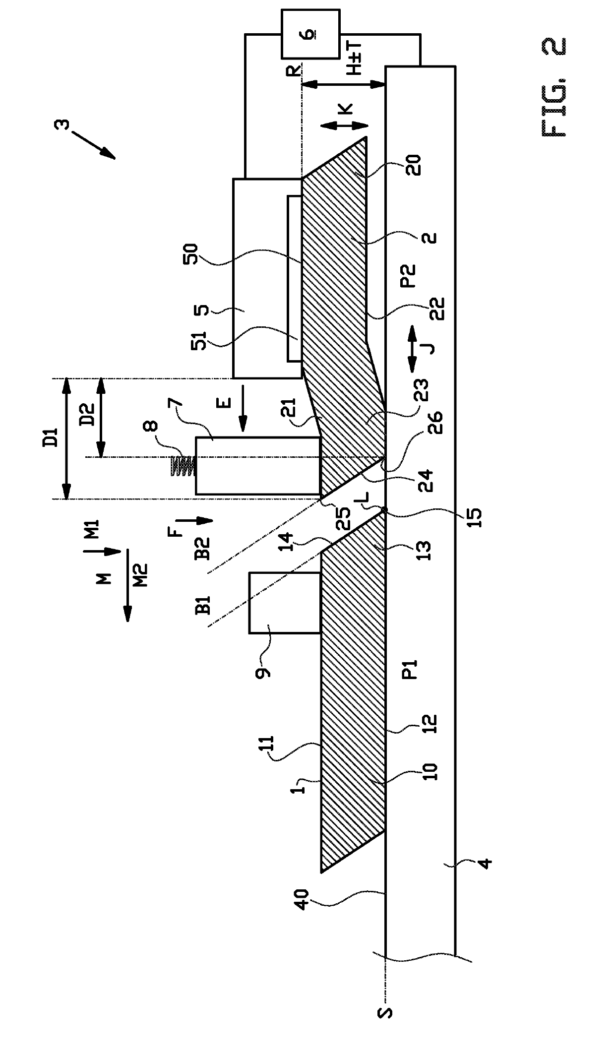
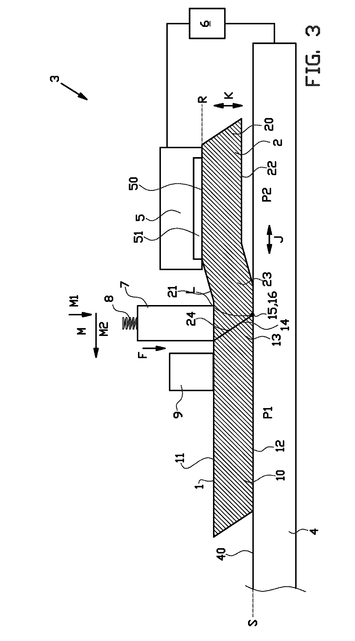
[0046]FIGS. 1-4 show a joining device 3 according to the invention during the steps of a method according to the invention for joining, pressing or splicing a first strip 1 to a second strip 2 to form a tire component.

[0047]The tire component is preferably a breaker ply or a body ply for building a green or unvulcanized tire. The first strip 1 comprises a strip body 10 with a top surface 11, a bottom surface 12, a trailing end 13 and a bevel end surface 14 that meets with the bottom surface 12 at a first bevel angle B1 to form a trailing edge 15. The second strip 2 comprises a strip body 20, a top surface 21, a bottom surface 22, a leading end 23 and a bevel end surface 24 that meets with the top surface 21 and the bottom surface 22 at a second bevel angle B2 to form a leading edge 25 and a recessed edge 26 respectively. The bevel angles B1, B2 of the respective strips 1, 2 are the same or substantially the same. The strip bodies 10, 20 are typically manufactured from unvulcanized, ...

second embodiment

[0065]FIGS. 5 and 6 show an alternative joining device 103 according to the invention. The alternative joining device 103 differs from the previously discussed joining device 3 in that the deflection member 107 is actively controlled. More in particular, the alternative joining device 103 comprises an alternative deflection actuator 108 that is operationally coupled to the deflection member 107 for actively driving the movement of the deflection member 107 in the deflection direction F between the flush position of FIG. 5 and the deflection position of FIG. 6.

third embodiment

[0066]FIGS. 8-11 show a further alternative joining device 203 according to the invention. The further alternative joining device 203 differs from the previously discussed joining devices 1, 103 in that it comprises an alternative retaining member 205 without a deflection member. Instead, the leading end 23 of the second strip 2 is allowed to freely project from the alternative retaining member 205 over the first projecting distance D1 in the projecting direction E. The alternative retaining member 205 is positionable in a joining position, as shown in FIG. 8, in which the retaining plane R extends above the second strip position P2 and declines or descends towards the joining line L under an oblique joining angle A with respect to the support plane S. The joining angle A is slightly exaggerated in the drawings to clearly demonstrate the invention. In practice, the joining angle A is preferably in a range of two to six degrees, preferably two to five degrees, most preferably three t...


PUM

PropertyMeasurementUnit
joining angleaaaaaaaaaa

Abstract

Disclosed is joining device for joining a trailing end of a first strip to a leading end of a second strip to form a tire component. The joining device includes a support member with a support surface and a retaining member with a retaining surface for retaining the second strip. The joining device is arranged for positioning the leading end of the second strip in a joining orientation in which said leading end is closer to the support plane than the rest. The joining device also includes a control unit for controlling a relative movement between the support member and the retaining member with a first component in a placement direction to place the leading end of the second strip and a second component in a joining direction to bring the leading end of the second strip into contact with the trailing end of the first strip.

Description

BACKGROUND[0001]The invention relates to a joining device and a method for joining strips to form a tire component.[0002]WO 2011 / 099846 A1 discloses a method for manufacturing a tyre from spliced strips, wherein the first strip is cut and the strip is placed on a discharge conveyor. After cutting the first strip a second strip is cut and placed on the discharge conveyor. After that the first and second strip are spliced. Between cutting the first strip and placing the second strip on the discharge conveyor the second strip is retained over the discharge conveyor, the projected separation distance between an end of the first strip and an end of the second strip to be spliced to said end is measured, and based on the measured separation distance the first strip is relatively displaced such with respect to the second strip that the end of the first strip is placed in the wanted position with respect to the second strip, after which the second strip is placed on the discharge conveyor.[...

Claims


Application Information

Patent Timeline
Patent Type & Authority Applications(United States)
IPC IPC(8): B29D30/42B29C65/78B29C65/00
CPCB29D30/42B29L2030/003B29C65/7841B29C65/7847B29C66/1142B29C66/1162B29C66/14B29C66/435B29C66/71B29C66/7212B29C66/72141B29C66/73752B29C66/8161B29C66/8322B29C66/8324B29D2030/422B29D2030/424B29C65/7802B29K2021/00B29K2305/00B29D2030/426B29D2030/428B29D2030/427
Inventor NIJLAND, GERRIT ROYVAN TIENHOVEN, JEROENZANDBERGEN, HUGO BARTOTTO, CORNELIS-JANVAN ASSENBERGH, KAREL JOHANNESHAITSMA, OTTEMEIJERS, PIETER CORNELIS
Owner VMI HOLLAND BV
Why Eureka
Try Eureka