Unmanned aerial vehicle fuselage

a technology for unmanned aerial vehicles and fuselages, which is applied in the direction of remote controlled aircraft, support structure mounting, printed circuit aspects, etc., can solve the problems of uav fuselage damage, uav electrical components are often subjected to torsional and/or compressive forces, and the effect of minimizing the transfer of vibration loads

Inactive Publication Date: 2019-09-12
VORTEX LABS INC
View PDF0 Cites 4 Cited by
  • Summary
  • Abstract
  • Description
  • Claims
  • Application Information

AI Technical Summary

Benefits of technology

[0008]Implementations of an unmanned aerial vehicle (UAV) fuselage are provided. In some implementations, the fuselage may be configured to minimize the transfer of vibration loads to electrical components secured thereto (e.g., a flight controller, motor controllers, a radio module, a GPS, a payload device, etc.). In this way, any disruption to the function of an electrical component sensitive to vibration loads is minimized or eliminated. In some implementations, the fuselage may be configured to encase one or more electrical components adapted to control the operation of a UAV. In this way, the encased electrical components may be protected from the environment (e.g., rain) and / or from direct impact should the UAV crash.

Problems solved by technology

Unmanned aerial vehicles (UAVs) are at constant risk of hard landings, collisions, and crashes.
Often, the fuselage of a UAV, or an electronic device mounted on the fuselage, is damaged during one of those events.
Under routine flight conditions, electrical components of a UAV are often subjected to torsional and / or compressive forces.
These forces can reduce the service life of affect electrical components and / or disrupt the proper function thereof.

Method used


Image

  • Unmanned aerial vehicle fuselage
  • Unmanned aerial vehicle fuselage
  • Unmanned aerial vehicle fuselage

Examples


Embodiment Construction

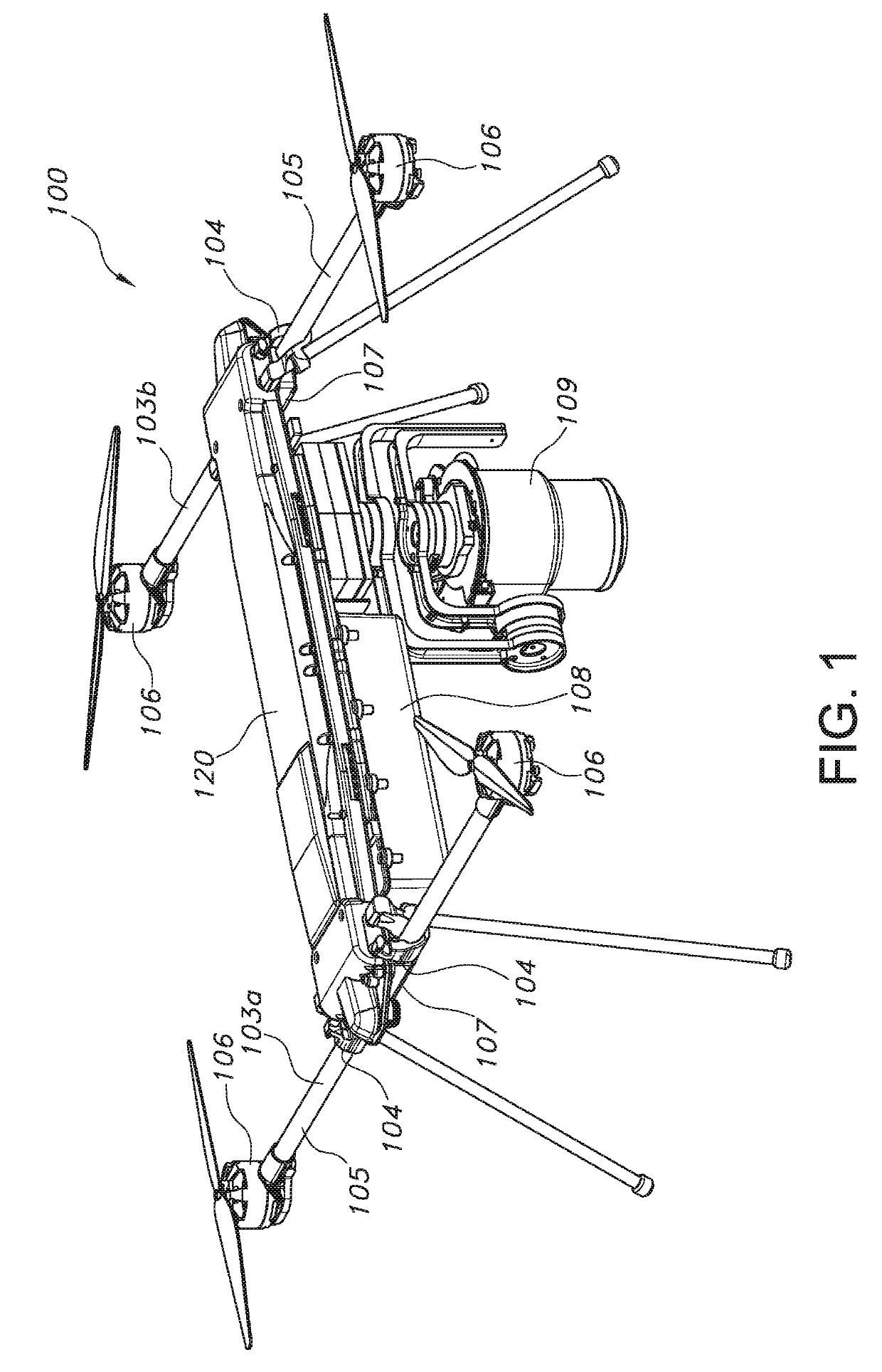
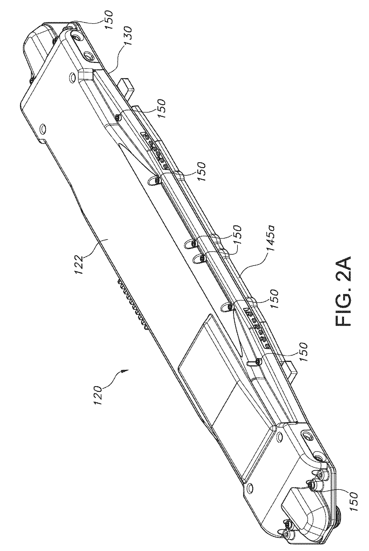
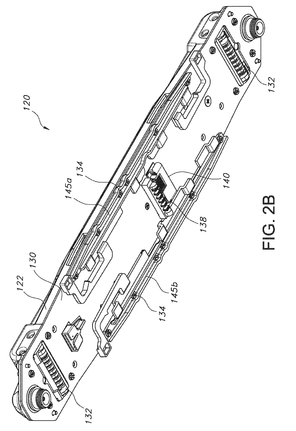
[0024]FIG. 1 illustrates an unmanned aerial vehicle (UAV) 100 having a fuselage 120 constructed in accordance with the principles of the present disclosure. In some implementations, the UAV fuselage 120 may be configured to minimize the transfer of vibration loads to electrical components secured thereto (e.g., a flight controller 110, motor controllers 112, a radio module 114, a Global Positioning System 116, a payload device 109, etc.). In this way, any disruption to the function of an electrical component sensitive to vibration loads (e.g., a sensor, a payload device, etc.) is minimized or eliminated. In some implementations, the UAV fuselage 120 may be configured to encase one or more electrical components adapted to control the operation of the UAV 100. In this way, the encased electrical components may be protected from the environment (e.g., rain) and / or from direct impact should the UAV 100 crash into the ground or another object.

[0025]As shown in FIG. 1, in some implementat...


PUM


Abstract

Implementations of an unmanned aerial vehicle (UAV) fuselage are provided. In some implementations, the fuselage comprises a frame having a shell removably secured thereto. The frame of the fuselage is made of printed circuit board (PCB) material that includes conductive tracks configured to conductively connect electrical components of the UAV. Due to the inherent rigidity of PCB material, the transfer of vibration loads to electrical components secured to the frame of the fuselage is minimized. While the shell is secured to the frame, an enclosure for any electrical components on the topside of the frame is formed. In this way, the encased electrical components may be protected from the environment (e.g., rain) and direct impact during a crash. In some implementations, the frame of the UAV fuselage may include a plurality of stiffening inserts that are positioned and configured to increase the rigidity of the frame.

Description

CROSS REFERENCE TO RELATED APPLICATION[0001]This application claims the benefit of U.S. Provisional Application Ser. No. 62 / 639,972, which was filed on Mar. 7, 2018, the entirety of which is incorporated herein by reference.TECHNICAL FIELD[0002]This disclosure relates to implementations of an unmanned aerial vehicle (UAV) fuselage.BACKGROUND[0003]An unmanned aerial vehicle (UAV), also known as a drone, is an aircraft without a human pilot aboard. UAV's are a component of an unmanned aircraft system (UAS) which includes a UAV and a ground-based controller that are connected by a two-way communication system. UAVs are often equipped with cameras, infrared devices, and other equipment according to its intended use, for example, surveillance, communication / information broadcasting, etc.[0004]Unmanned aerial vehicles (UAVs) are at constant risk of hard landings, collisions, and crashes. Often, the fuselage of a UAV, or an electronic device mounted on the fuselage, is damaged during one o...

Claims


Application Information

Patent Timeline
Patent Type & Authority Applications(United States)
IPC IPC(8): B64C1/06B64C39/02B64C27/32H05K5/00H05K1/18
CPCB64C1/062H05K1/182B64C39/024H05K5/0026B64C27/32H01R12/7088B64C2201/165B64C2201/108H05K2201/10189B64C2201/027H05K7/1417B64C1/06B64C2001/0054B64D2221/00
Inventor PIKE, JAMES THOMASGIESSEL, DAVIDHILDESHEIM, BRUCE
Owner VORTEX LABS INC
Why Eureka
Try Eureka