
Automatic correlation of dynamic system events within computing devices

a dynamic system and event technology, applied in the field of system logs within electronic computing devices, can solve the problems of difficult, cumbersome, and difficult, and achieve the effects of reducing the number of unique log entries

Active Publication Date: 2019-09-19
CISCO TECH INC
View PDF21 Cites 0 Cited by
  • Summary
  • Abstract
  • Description
  • Claims
  • Application Information

AI Technical Summary

Benefits of technology

The present patent is about a system for automatically analyzing log entries in electronic devices to diagnose system problems. The system uses an event log that is structured as a collection of tree-like graphs to identify and analyze the relationships between log entries. The system can receive information about system events and create new event nodes within the log as needed. The system can also delete existing event nodes and provide a user interface for accessing the log. The technical effects of the system include improved efficiency and accuracy in identifying and analyzing system problems, as well as reduced error and incomplete diagnosis.

Problems solved by technology

Manually determining which log entries relate to a given problem, however, is in general a challenging, cumbersome, and error prone endeavor.
It might take many hours to sort through hundreds, thousands, or millions of unique log entries to identify those that pertain to the issue being investigated.
The process is also prone to error.
If the administrator inadvertently discounts a single log entry that represents an important event relating to the problem, the conclusion of the analysis will usually be incorrect or incomplete.
Administrators often fail to correlate important events that relate to a problem, leaving the diagnosis of the problem incomplete.
These system log analysis challenges tend to increase as devices become more and more complex.
Some complex systems, such as network routing and switching equipment, may log thousands of unique system events.
It is nearly impossible for an administrator to fully understand what each log entry indicates and how each event might be linked to one another.

Method used


Image

  • Automatic correlation of dynamic system events within computing devices
  • Automatic correlation of dynamic system events within computing devices
  • Automatic correlation of dynamic system events within computing devices

Examples


Embodiment Construction

Overview

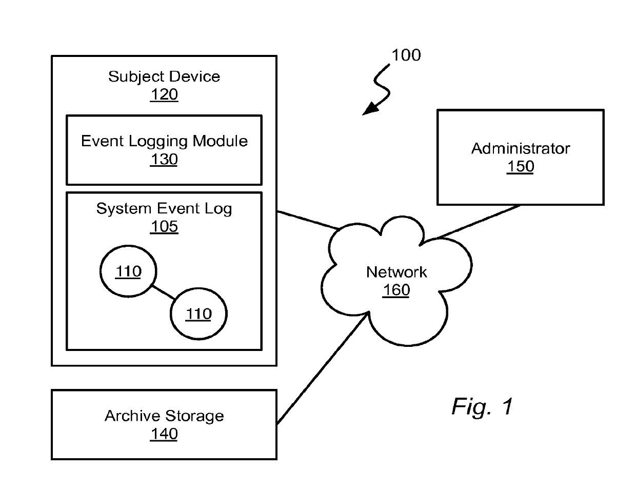
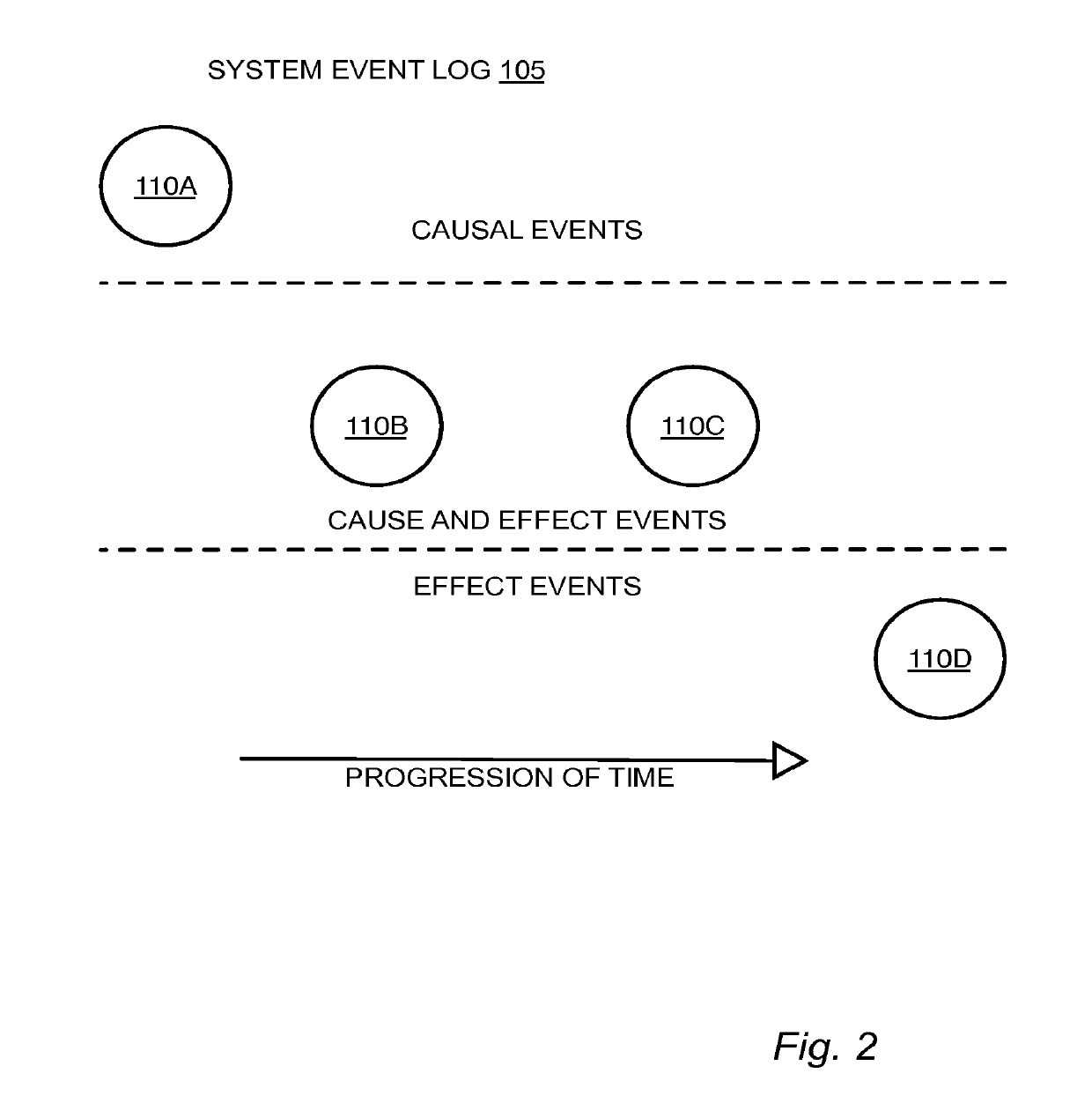
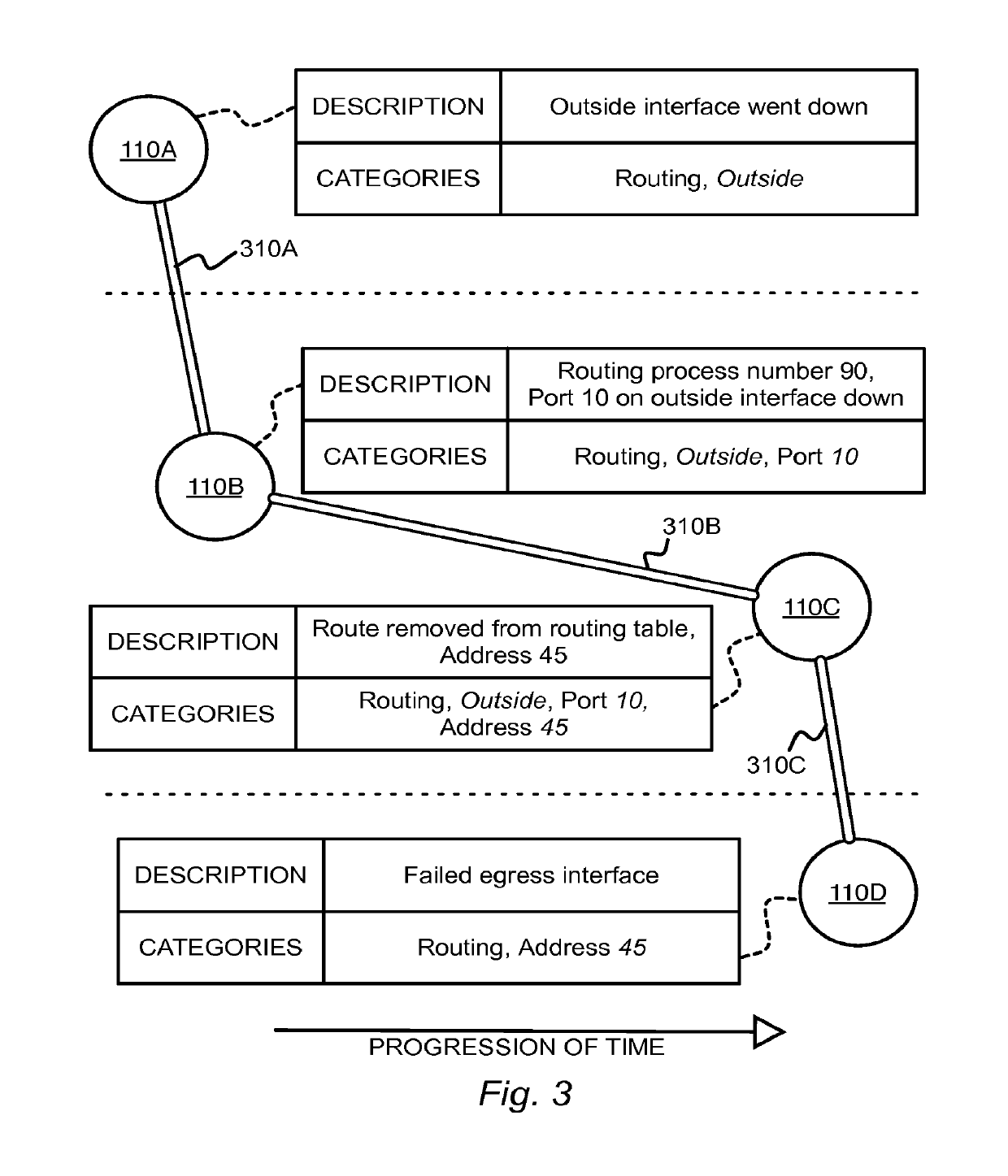
[0012]The methods and systems described herein enable logging system events within an electronic machine using an event log structured as a collection of tree-like graphs. Information regarding an event to be logged may be received. A new event node may be created within the event log for the received event information. One or more existing event nodes within the event log may be identified as having possibly caused the received event. One or more causal links may be created within the event log between the new event node and the one or more identified existing event nodes. The new event node may be stored as an unattached root node in response to not identifying an existing event node that may have caused the received event.

[0013]The functionality of the various example embodiments will be explained in more detail in the following description, read in conjunction with the figures illustrating the program flow. Turning now to the drawings, in which like numerals indicate lik...


PUM


Abstract

Systems and methods are described herein for logging system events within an electronic machine using an event log structured as a collection of tree-like cause and effect graphs. An event to be logged may be received. A new event node may be created within the event log for the received event. One or more existing event nodes within the event log may be identified as having possibly caused the received event. One or more causal links may be created within the event log between the new event node and the one or more identified existing event nodes. The new event node may be stored as an unattached root node in response to not identifying an existing event node that may have caused the received event.

Description

TECHNICAL FIELD[0001]The present disclosure relates generally to system logs within electronic computing devices.BACKGROUND[0002]System logs are valuable tools for administrators. Examining system logs may help diagnose the cause of system problems. Manually determining which log entries relate to a given problem, however, is in general a challenging, cumbersome, and error prone endeavor.[0003]It might take many hours to sort through hundreds, thousands, or millions of unique log entries to identify those that pertain to the issue being investigated. Once the relevant messages are identified, it requires expertise on the part of the administrator to effectively parse the logs to understand the cause and effect relationships between the records. The process often requires expertise with tools, such as text file sorting and searching programs and scripts. The process is also prone to error. If the administrator inadvertently discounts a single log entry that represents an important ev...

Claims


Application Information

Patent Timeline
Patent Type & Authority Applications(United States)
IPC IPC(8): G06F11/07G06F16/901G06F16/2455G06F16/22G06F16/17G06F17/22G06F11/36H04L12/24
CPCG06F11/0775G06F16/1734G06F16/2455G06F11/0751H04L41/069H04L41/0636H04L41/22G06F11/079G06F16/9027G06F17/2241G06F11/0709G06F16/2246G06F11/0787G06F11/366G06F40/137H04L45/00G06F11/07
Inventor JOHNSTON, JAY KEMPERWHITE, JR., DAVID C.DREIER, CHRISTOPHER BLAYNE
Owner CISCO TECH INC
Learn More