Tilt-Safe, High-Capacity Lift Device

Active Publication Date: 2019-09-26
GAITHER TOOL COMPANY
View PDF5 Cites 2 Cited by
  • Summary
  • Abstract
  • Description
  • Claims
  • Application Information

AI Technical Summary

Benefits of technology

[0028]One method of manufacturing a jack may include providing a frame sealed to a containment vessel, providing a pump operably connected between the base and the containment vessel, providing a cylinder within the containment vessel, providing a piston operably coupled to travel within the cylinder, operably connecting a system of valves to selectively pass a hydraulic fluid from the containment vessel through the pump to the cylinder at a pressure effective to lift a load supported by the cylinder and to release the hydraul

Problems solved by technology

Thus, outside of the lever, the packag

Method used


Image

  • Tilt-Safe, High-Capacity Lift Device
  • Tilt-Safe, High-Capacity Lift Device
  • Tilt-Safe, High-Capacity Lift Device

Examples


first embodiment

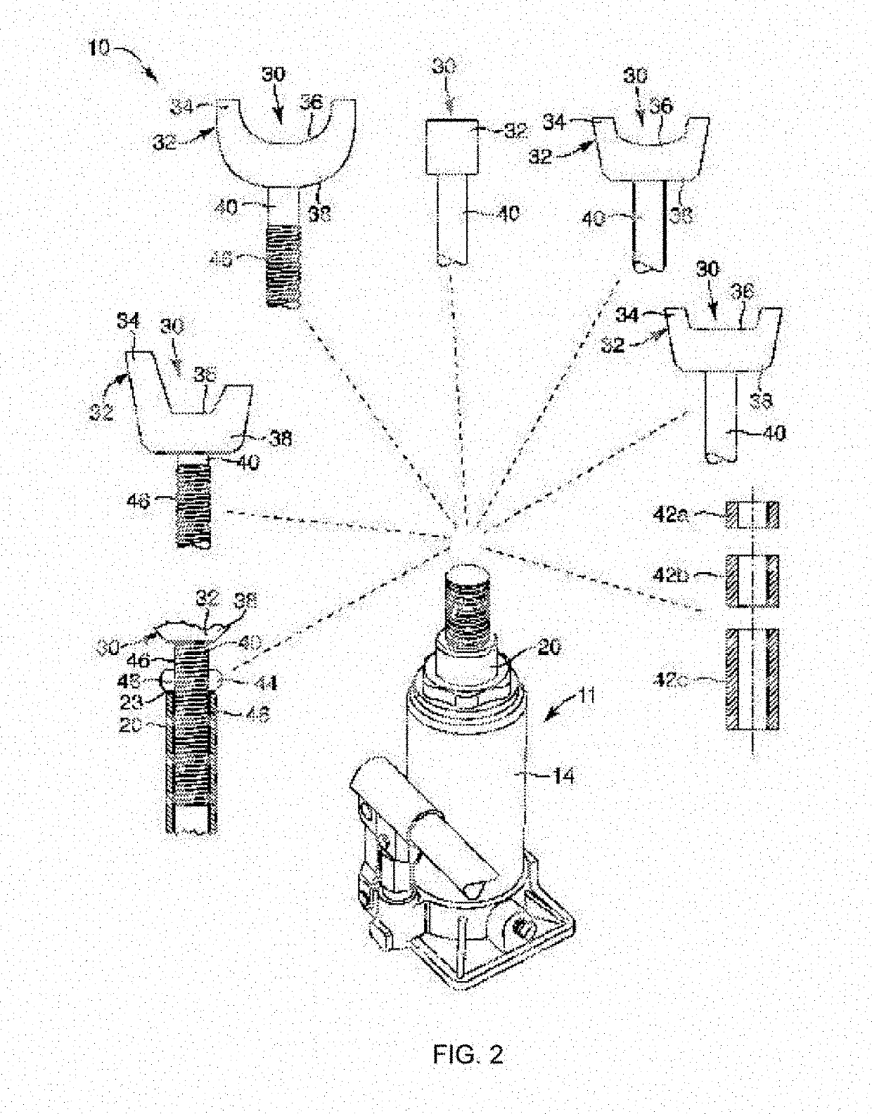
[0110]Referring to FIG. 2, while continuing to refer generally to FIGS. 1 through 12, one may begin viewing alternative embodiments of heads 30 for the jack 11 clockwise from the extreme left. In the first embodiment, the shaft 40 is threaded to receive a collar 44 or ring 44. The collar 44 is threaded to spin up and down on the mutually engaged threads of the shaft 40 and collar 44. The threads 46 on the shaft 40 engage with the threads 48 on the collar 44 or ring 44. The collar 44 may be knurled, textured, fluted (having vertical ribs and intervening valleys for gripping), angled like a nut on a bolt, or the like.

[0111]The collar 44 without substantial frictional loads between itself and the upper annular surface 23 of the piston 20 turns comparatively freely. With proper tolerances and some modicum of lubrication, the collar 44 will rotate about the shaft 40, thereby advancing up and down the length of the shaft 40. In the illustrated embodiment, no engagement for vertical loadin...

fifth embodiment

[0118]The fifth embodiment from the left is actually a cylindrical or cup shaped yoke 32 on a shaft 40. The shaft 40 may actually fit inside an inner diameter of a tubular yoke 32. A cavity above the shaft 40 and within the yoke 32 is sized to receive a “U” bolt. Meanwhile, the “U” bolt nut fits against the upper surface of the yoke 32, thus providing a convenient lifting location.

sixth embodiment

[0119]The sixth embodiment provides comparatively lower, typically even, retainers 34 restraining the lifted load and the yoke 32 with respect to one another. Thus, this head 30 need not rely on an exact fit, but simply provides some restraint against relative lateral motion occurring between the yoke 32 and the lifted load.

[0120]It has been found that a set of spacers 42 or risers 42 may be provided in the series of sizes. These may simply be based on individual units additive to one another. However, in one embodiment, one shim 42a may be one unit of height total, while another 42b is two units of height tall. A third 42c has four units of height. Thus, all combinations between one unit and seven units of height are available, in individual unit increments. A proper stack of one, two, or three at the spacers 42 goes on a shaft 40 before that shaft 40 is inserted into the piston 20.

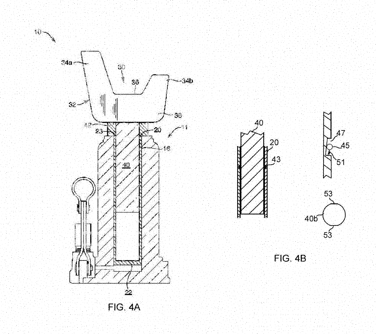
[0121]Referring to FIGS. 3 and 4A, while continuing to refer generally to FIGS. 1 through 12, a cutaw...


PUM


Abstract

A lifting device with a head cavity in the lifting member shaped to accept a removable lifting head. The head cavity in the lifting device—e.g., the piston of a bottle jack—may be provided with threads, or may have the threads removed. A yoke fitted on the lifting head provides registration, horizontal restraint, or both against a lifted object, component, or surface to prevent sliding off the lifting head while in use. In a smooth-walled-shaft embodiment, a set of risers (spacers, adjusters, trims, or shims) serves to adjust an extension height of the shaft, elevating the lifting head with respect to the piston prior to beginning to lift the hydraulic piston.

Description

CROSS-REFERENCE TO RELATED APPLICATIONS[0001]The present application claims priority from, and incorporates by reference in its entirety, U.S. patent application Ser. No. 15 / 260,167 filed Sep. 8, 2016.BACKGROUNDField of the Invention[0002]This invention relates to hydraulic jacks and, more particularly, to novel systems and methods for hydraulic “bottle jacks” load rated for heavy vehicles under which they are used.Description of Related Art[0003]Bottle jacks are small, portable, self-contained systems. Relying on hydraulic oil, they operate on certain principles of fluid mechanics. Being hand-portable, they cannot have all the mechanisms, protections, conveniences, wheels, bearing widths or lengths, size, stabilization, visibility and so forth possible for rolling floor jacks (also called trolley jacks) common in commercial repair shops.[0004]At the top of the piston is typically a head. That head is a problem. The relatively small cross sectional area of a head is almost universal...

Claims


Application Information

Patent Timeline
IPC IPC(8): B66F3/36
CPCB66F2700/055B66F3/36B66F2700/052B66F3/25B66F3/26B66F3/24B66F3/42B66F5/04
Inventor MOORE, JASON THOMAS
Owner GAITHER TOOL COMPANY
Why Eureka
Try Eureka