Sphygmomanometer, and method and device for measuring blood pressure

a blood pressure and manometer technology, applied in the field of sphygmomanometers, can solve problems such as blood pressure value measurement errors, and achieve the effect of accurately measuring blood pressur

Pending Publication Date: 2019-10-03
ORMON CORP +1
View PDF2 Cites 2 Cited by
  • Summary
  • Abstract
  • Description
  • Claims
  • Application Information

AI Technical Summary

Benefits of technology

[0006]Therefore, an object of the present invention is to provide a sphygmomanometer, a blood-pressure measurement method, and a device capable of accurately measuring a blood pressure even when the blood pressure is measured by pressing a blood-pressure measurement cuff via an intervening member.

Problems solved by technology

As a result, the pressing force of the blood-pressure measurement cuff to the measurement site is not uniform in the width direction, causing a problem that a measurement error occurs in a blood pressure value.

Method used


Image

  • Sphygmomanometer, and method and device for measuring blood pressure
  • Sphygmomanometer, and method and device for measuring blood pressure
  • Sphygmomanometer, and method and device for measuring blood pressure

Examples


Embodiment Construction

[0044]Embodiments of the present invention will now be described in detail with reference to the drawings.

(Configuration of Sphygmomanometer)

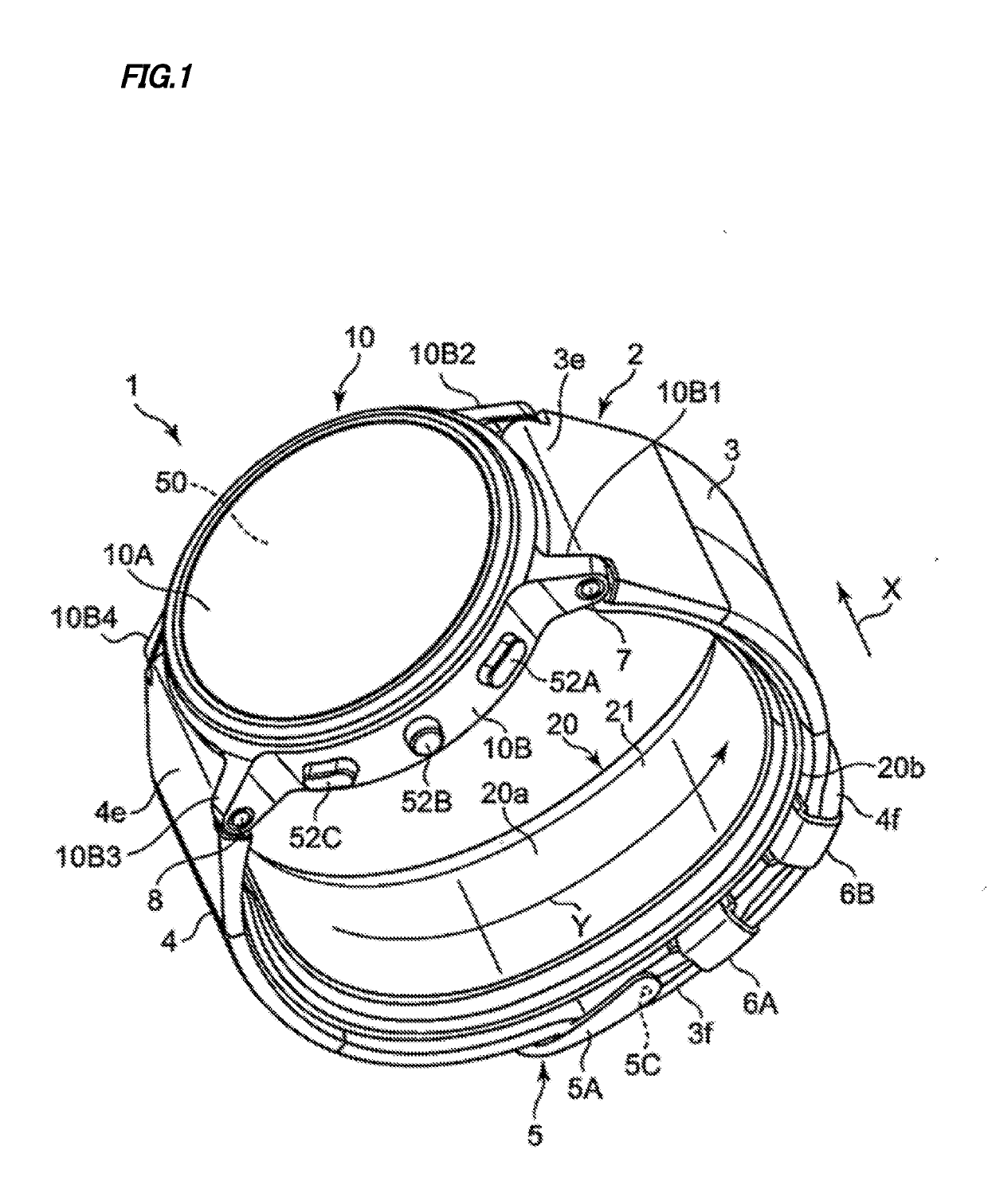
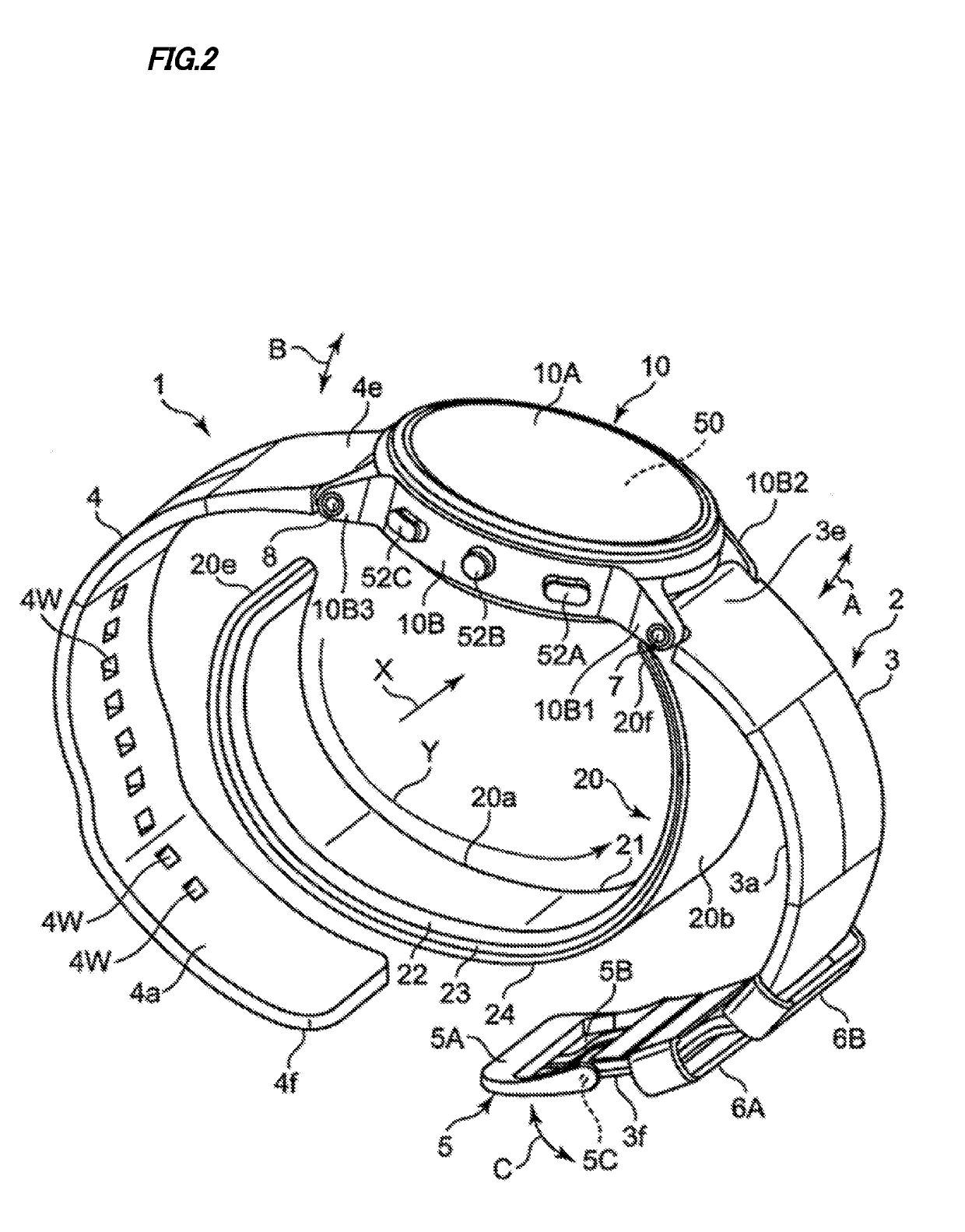
[0045]FIG. 1 shows an appearance of a sphygmomanometer (generally denoted by reference numeral 1) of an embodiment of the present invention with a belt 2 fastened as viewed obliquely. FIG. 2 shows the appearance of the sphygmomanometer 1 with the belt 2 released as viewed obliquely.

[0046]As shown in these figures, the sphygmomanometer 1 roughly includes a main body 10, the belt 2 extended from the main body 10 and to be worn to wrap a measurement site (in this example, as shown in FIG. 13C described later, a left wrist 90 is supposed to be the measurement site), and a strap-shaped cuff structure 20 having one end 20f attached to the main body 10. The dimension in a width direction X of the belt 2 is set to 29 mm in this example. The thickness of the belt 2 is set to 2 mm in this example.

[0047]In this example, the main body 10 has a substantiall...


PUM


Abstract

A sphygmomanometer includes: a bag-shaped sensing cuff to be worn to wrap a measurement site; a back plate disposed on the sensing cuff along a surface opposite to the measurement site; a pressing member for pressing the back plate toward the measurement site; and a blood-pressure calculating part calculating a blood pressure based on a pressure of a fluid stored in the sensing cuff. Regarding a longitudinal direction perpendicular to a circumferential direction of the measurement site to be wrapped by the sensing cuff, a surface facing the measurement site in edge potions on both sides in a width direction along the longitudinal direction of the back plate is curved in a direction away from the measurement site toward tips.

Description

CROSS-REFERENCE TO RELATED APPLICATION[0001]This is a continuation application of International Application No. PCT / JP2017 / 042370, with an International filing date of Nov. 27, 2017, which claims priority of Japanese Patent Application No. 2016-256030 filed on Dec. 28, 2016, the entire content of which is hereby incorporated by reference.TECHNICAL FIELD[0002]The present invention relates to a sphygmomanometer and, more particularly, to a sphygmomanometer comprising a belt worn to wrap a measurement site and a main body equipped with a pump. The present invention also relates to a blood-pressure measurement method for measuring a blood pressure at a measurement site. The present invention further relates to a device having a blood-pressure measurement function.BACKGROUND ART[0003]For example, as disclosed in Patent Document 1 (Japanese Laid-Open Patent Publication No. 11-309119), a conventionally known sphygmomanometer of this type has a cuff wound around a wrist that is a measuremen...

Claims


Application Information

Patent Timeline
Patent Type & Authority Applications(United States)
IPC IPC(8): A61B5/0235A61B5/022A61B5/00
CPCA61B5/6831A61B5/681A61B5/02233A61B5/0235A61B5/02A61B5/022
Inventor IWATA, SHOHEINISHIOKA, TAKANORITAMPO, AKIRASANO, YOSHIHIKOKUBO, TAKESHIHIGASHIMURA, YU
Owner ORMON CORP
Why Eureka
Try Eureka