
Bowling Balls and Methods of Forming the Same

a technology of forming methods and balls, applied in the field of bowling balls, can solve the problems of limiting the extent of customization, voiding the warranty of balls, and affecting the durability of drilled balls, so as to reduce warranty costs, improve durability, and improve the effect of drilled balls

Inactive Publication Date: 2019-10-03
BRUNSWICK BOWLING PROD
View PDF6 Cites 0 Cited by
  • Summary
  • Abstract
  • Description
  • Claims
  • Application Information

AI Technical Summary

Benefits of technology

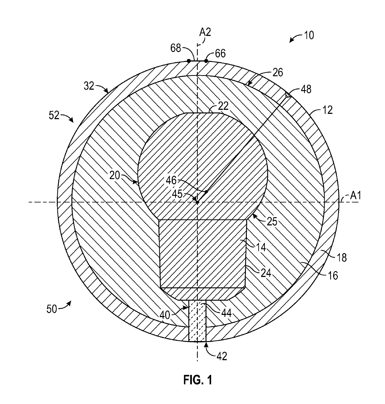
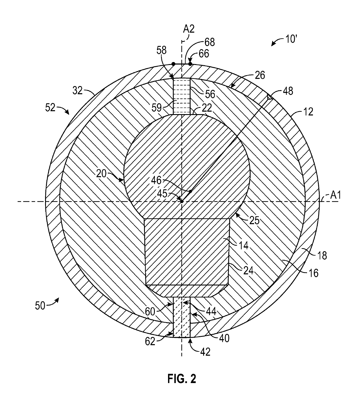
The present patent allows for bowling balls to be made that can have drilling restrictions removed while still meeting USBC regulations. This is achieved by moving the riser pin support to the opposite side of the inner core, which causes the riser pin to be about 180 degrees opposite from its current position. As a result, gripping holes can be placed and patterned more flexibly to achieve better performance preferences for bowlers. This reduces durability issues and warranty costs, while also making drilling more flexible.

Problems solved by technology

Bowling balls, however, do still need to meet industry standard specifications, and / or regulations, such as those promulgated by the United States Bowling Congress (“USBC”), which can thus limit the extent of such customization.
But, because the riser pin forms a break or open area in the cover stocks, it creates a weakened spot or area in one or more layers of the ball, the cover layer or cover stock of the ball can fail or crack during drilling and / or over time with use if the drilled gripping holes are formed too close to the riser pin.
Bowling ball manufacturers therefore generally set warranty limits regarding the proximity of the riser pin to the gripping holes, and drilling one or more gripping holes closer to the riser pin than permitted by such limits can void the ball's warranty.
Unfortunately, the optimal placement area and patterning for the drilled gripping holes, e.g., the location of the gripping holes selected for maximizing the performance and tracking characteristics of the bowling ball by a bowler, may conflict with such warranty restrictions.

Method used


Image

  • Bowling Balls and Methods of Forming the Same
  • Bowling Balls and Methods of Forming the Same
  • Bowling Balls and Methods of Forming the Same

Examples


Embodiment Construction

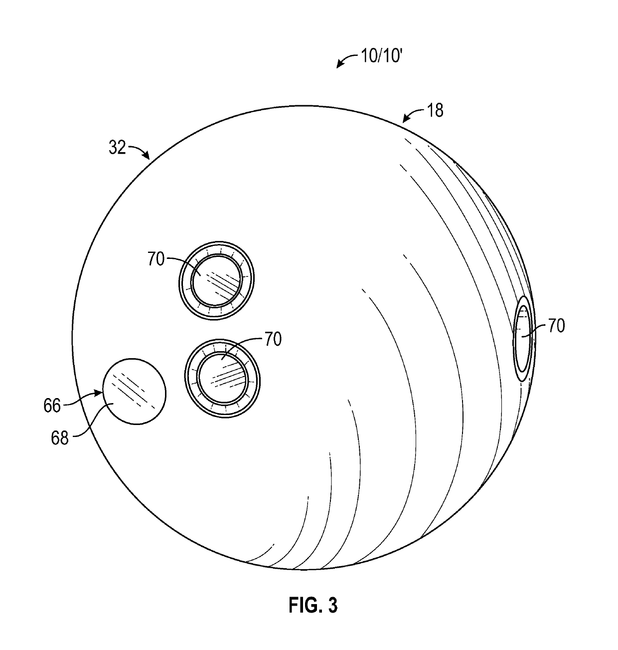
[0031]Referring now to the drawings wherein like reference numerals designate corresponding parts throughout the several views, FIGS. 1-5 illustrate components of bowling balls and methods for forming bowling balls according to principles of the present disclosure. The following description is provided as an enabling teaching of embodiments of this disclosure. Those skilled in the relevant art will recognize that many changes can be made to the embodiments described, while still obtaining the beneficial results. It will also be apparent that some of the desired benefits of the embodiments described can be obtained by selecting some of the features of the embodiments without utilizing other features. Accordingly, those who work in the art will recognize that many modifications and adaptations to the embodiments described are possible and may even be desirable in certain circumstances. Thus, the following description is provided as illustrative of the principles of the embodiments of ...


PUM

PropertyMeasurementUnit
Angleaaaaaaaaaa
Lengthaaaaaaaaaa
Equivalent weightaaaaaaaaaa

Abstract

A bowling ball can have an inner core layer that is shaped, constructed, and / or configured to provide the bowling ball with one or more prescribed properties or characteristics, and a cover stock layer comprising a liquid curable material received about the inner core layer. The bowling ball further has a riser pin feature that is at least partially defined by a passage extending through at least the cover stock layer and in which a filler material is received. The riser pin feature can be located in an opposite hemisphere of the bowling ball from a hemisphere including the true center of gravity and a marked heavy spot of the bowling ball and can be arranged within about 1 inch of an end of the Low Radius of Gyration Axis of the bowling ball.

Description

TECHNICAL FIELD[0001]The present disclosure is directed to bowling, and more specifically to bowling balls.DISCUSSION OF RELATED ART[0002]As bowling has increased in popularity, ball customization, such as for achieving more user specific gripping patterns, performance characteristic, aesthetics, etc., has likewise increased. Bowling balls, however, do still need to meet industry standard specifications, and / or regulations, such as those promulgated by the United States Bowling Congress (“USBC”), which can thus limit the extent of such customization. For example, USBC regulations require one end of the low radius of gyration (RG) axis of the ball for high performance bowling balls be within a 1″ radius of the center of the riser pin used for supporting the core within the sphere of the ball during its formation.[0003]To comply with such regulations, the riser pin traditionally is positioned within the same hemisphere as the true center of gravity and the marked heavy spot of the bal...

Claims


Application Information

Patent Timeline
IPC IPC(8): A63B37/00A63B37/10A63B37/04A63B45/00
CPCA63B37/0001A63B37/10B29C37/0025A63B37/04A63B45/00B29C2037/0035B29C37/0028A63B2209/00A63B2071/0694A63B2243/0054
Inventor EDWARDS, RAYMOND M.ORLIKOWSKI, WILLIAM
Owner BRUNSWICK BOWLING PROD
Learn More