
Wall mounting assembly

Active Publication Date: 2019-10-03
FOOD GRADE SOLUTIONS LLC
View PDF0 Cites 4 Cited by
  • Summary
  • Abstract
  • Description
  • Claims
  • Application Information

AI Technical Summary

Benefits of technology

The invention is a wall mount assembly that can keep things like pipes or tubes securely attached to a wall and help keep them clean and easily inspected. This makes it suitable for use in food and pharmaceutical grade installations.

Problems solved by technology

These conventional mounting systems are difficult to inspect and clean and tend to be prone to contamination, thus rendering them inherently dirty and possibly leading to food and drug safety issues.
As will be appreciated, upward facing surfaces are especially at risk for collecting contaminants, falling debris, and water from wash downs.
Further, any surface that cannot be easily inspected or cleaned can be susceptible to harboring filth and mildew and allow for collection of hazardous dust from food preparation or manufacturing process.
For example, some conventional mounting systems are typically mounted directly onto the wall and the systems are designed such that small gaps exist between the mounting system and the wall, and these gaps are not easily accessible for inspection or cleaning.
As another example, some conventional mounting systems include exposed threaded surfaces that are difficult to clean and tend to collect debris.
Moreover, most conventional mounting systems cannot be securely fastened to laminated foam wall panels, as are commonly used in the wall structures of food and pharmaceutical processing facilities.
The wall mounting screws found in many conventional mounting systems are not ideal for gripping the foam interior of such wall panels and staying in place for mounting a load, such as a conduit or pipe or the like, and do not provide a suitable mounting assembly for food preparation areas to prevent collection of dust or allow for cleaning of the mounting assembly.

Method used


Image

  • Wall mounting assembly
  • Wall mounting assembly
  • Wall mounting assembly

Examples


Embodiment Construction

[0027]The description that follows describes, illustrates and exemplifies one or more embodiments of the invention in accordance with its principles. This description is not provided to limit the invention to the embodiment(s) described herein, but rather to explain and teach the principles of the invention in order to enable one of ordinary skill in the art to understand these principles and, with that understanding, be able to apply them to practice not only the embodiment(s) described herein, but also any other embodiment that may come to mind in accordance with these principles. The scope of the invention is intended to cover all such embodiments that may fall within the scope of the appended claims, either literally or under the doctrine of equivalents.

[0028]It should be noted that in the description and drawings, like or substantially similar elements may be labeled with the same reference numerals. However, sometimes these elements may be labeled with differing numbers or ser...


PUM


Abstract

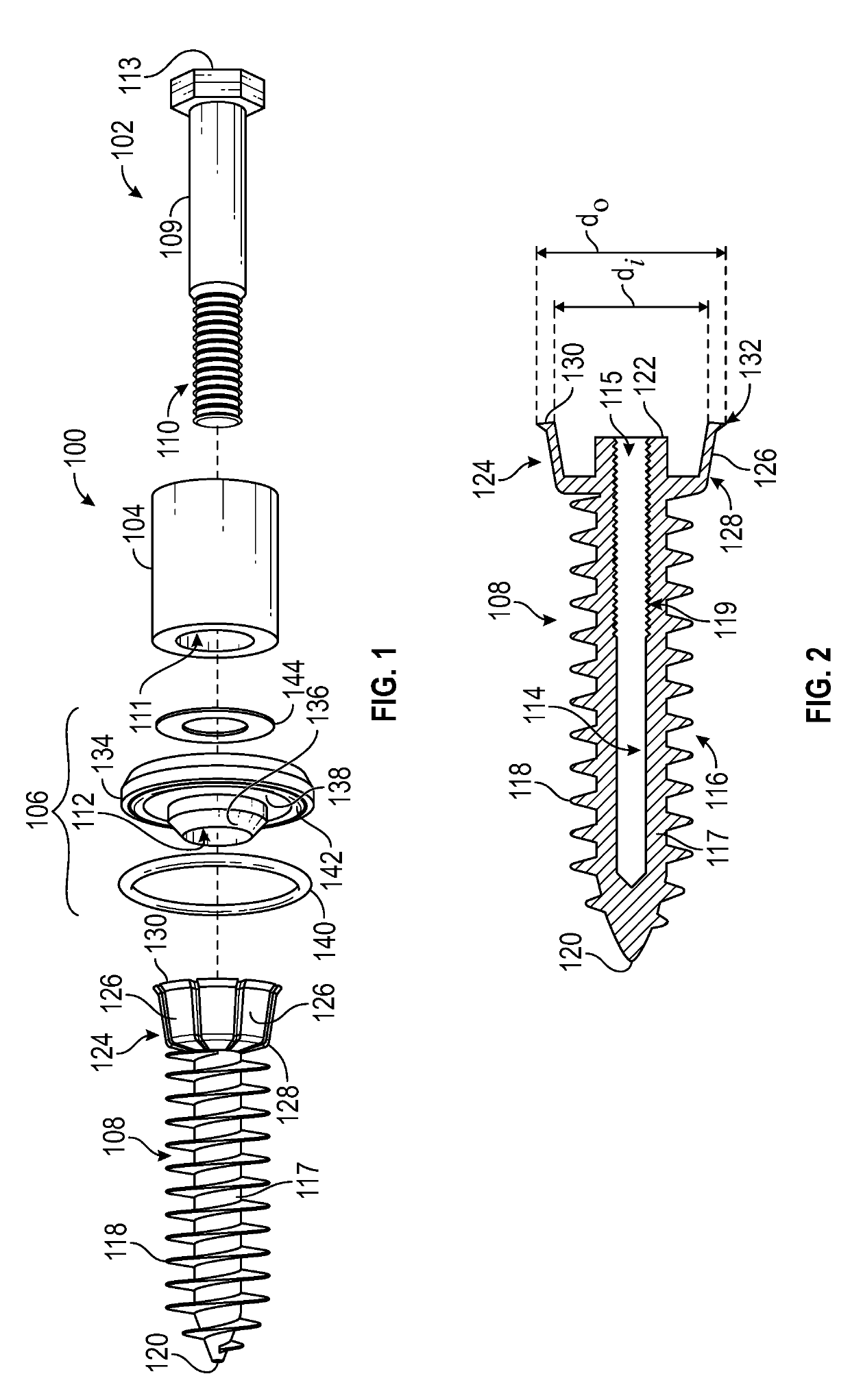
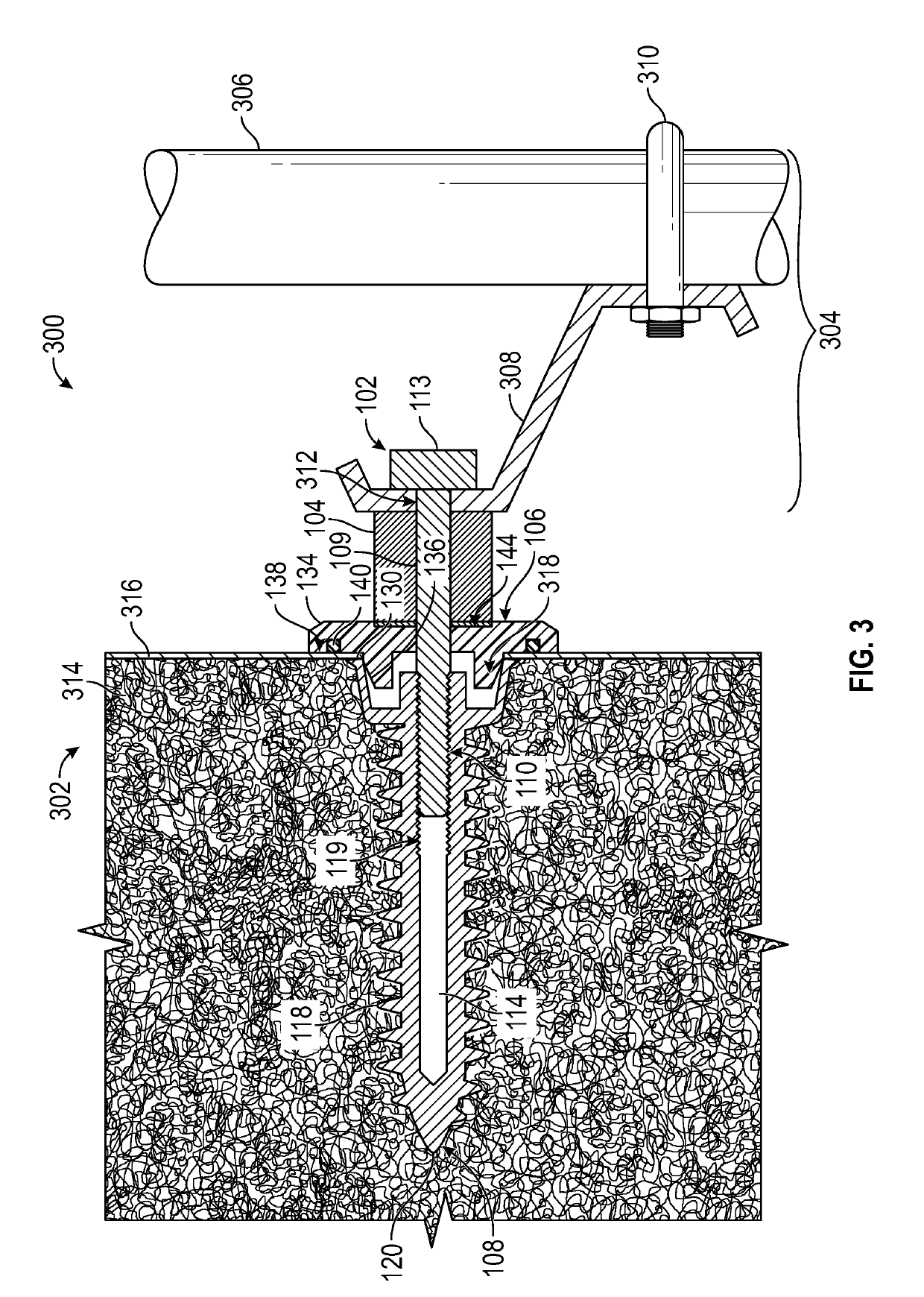
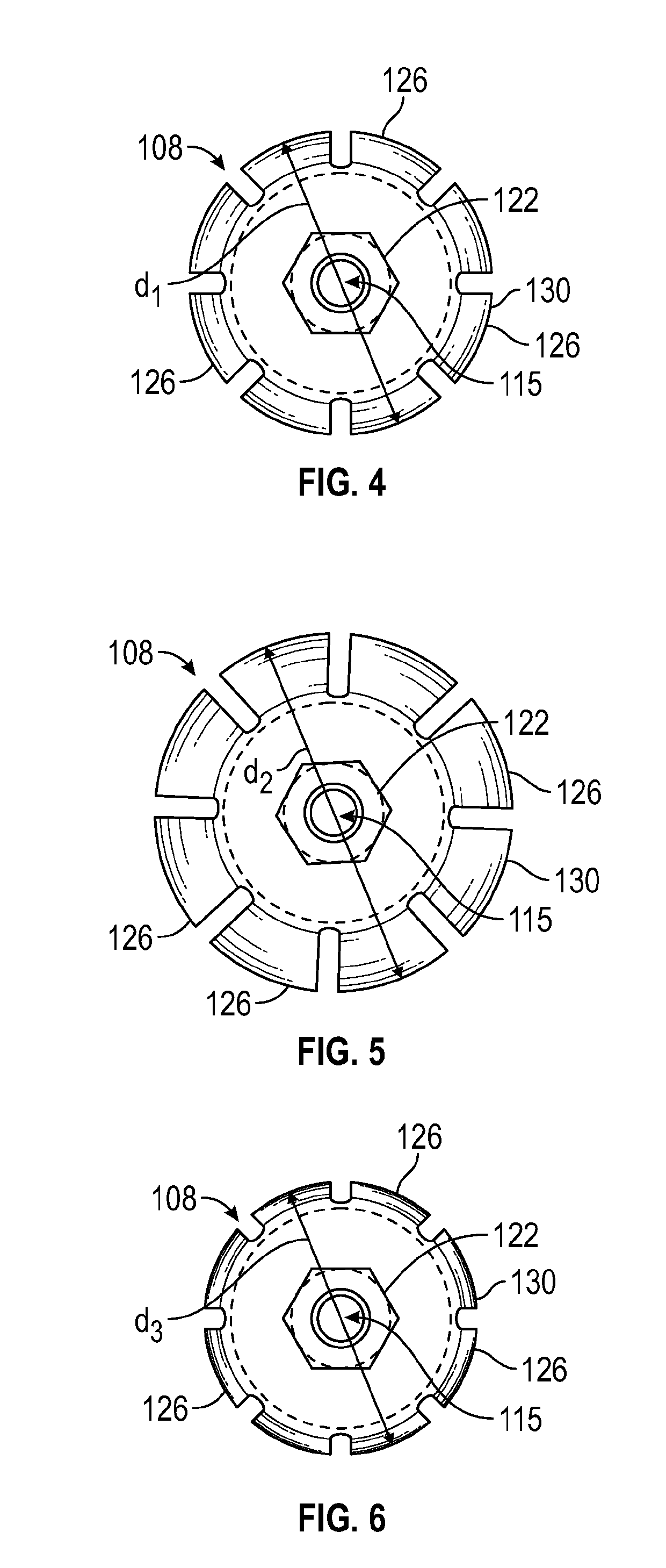
A mounting assembly is provided for securing an element to a wall structure having a laminate outer cover residing adjacent to an internal thickness of compressible material. The assembly includes an anchor for engaging the wall structure and comprising a threaded outer wall for securing the anchor within the wall thickness, an elongated internal passageway for receiving an extent of an elongated fastener, and a deformable upper crown arranged about an open end of the passageway; a strut assembly coupled to the supported element; and an elongated fastener for securing the strut assembly to the anchor and wall structure. Other embodiments include a fastener assembly kit comprising a plurality of separate components to be assembled together to mount a strut member to a laminated foam wall panel, the components including an anchor, a washer assembly, a spacer, and an elongated fastener for securing the components to the wall panel.

Description

BACKGROUND[0001]The description that follows relates to a wall mounting assembly for securing an object to a wall or other support structure. More specifically, the description relates to a wall mounting assembly intended to be used in food processing, pharmaceutical processing, and other facilities that require a high degree of cleanliness or enhanced sanitation.[0002]Food processing and pharmaceutical processing facilities typically use conventional mounting systems to install pipes, conduit, and tubes. These conventional mounting systems are difficult to inspect and clean and tend to be prone to contamination, thus rendering them inherently dirty and possibly leading to food and drug safety issues. For example, conventional mounting systems may be used to mount pipes, conduits, and tubes to vertical and horizontal surfaces (e.g., walls). As will be appreciated, upward facing surfaces are especially at risk for collecting contaminants, falling debris, and water from wash downs. Wh...

Claims


Application Information

Patent Timeline
IPC IPC(8): F16B13/00
CPCF16M13/02F16B2013/009F16B13/14F16L3/00E04F13/0866F16B13/003F16B5/065F16B5/0685F16B19/02F16B37/127F16B43/001F16L3/1091F16L2201/40F16B13/0858
Inventor TJERRILD, JAMES
Owner FOOD GRADE SOLUTIONS LLC
Features
  • Generate Ideas
  • Intellectual Property
  • Life Sciences
  • Materials
  • Tech Scout
  • Unparalleled Data Quality
  • Higher Quality Content
  • 60% Fewer Hallucinations
Learn More