
Cascade Varistor having Improvecd Energy Handling Capabilities

a varistor and cascade technology, applied in the field of varistor arrays, can solve the problems of low operating current, reduced durability, and general limited current and energy handling ability of varistor arrays

Active Publication Date: 2019-10-03
KYOCERA AVX COMPONENTS CORP
View PDF3 Cites 6 Cited by
  • Summary
  • Abstract
  • Description
  • Claims
  • Application Information

AI Technical Summary

Benefits of technology

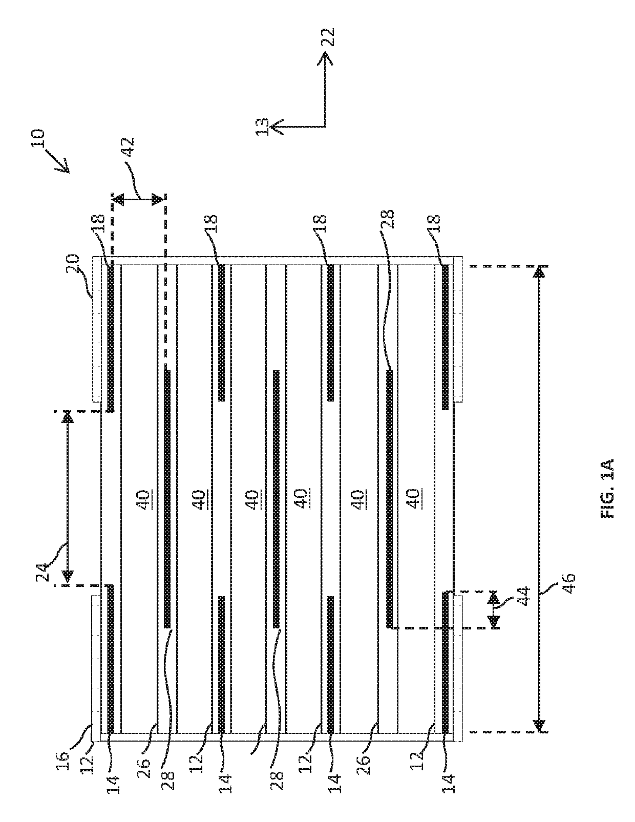
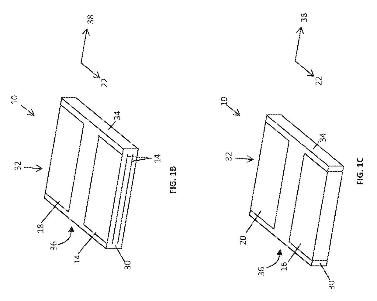
The present disclosure provides various embodiments of a varistor with a rectangular configuration. The varistor includes a first terminal and a second terminal, and an active electrode layer adjacent to each terminal with an active electrode end gap and a floating electrode layer with a floating electrode gap. The ratio of the active electrode end gap to the floating electrode gap is greater than about 2. In some embodiments, the varistor also includes a plurality of active electrode layers and floating electrode layers interleaved in a cascade configuration. The capacitance of the varistor is less than about 100 μF. Additionally, the specific transient energy capability of the varistor is greater than about 1×10⁷ J / m3. These technical effects provide improved performance and reliability of the varistor in various applications.

Problems solved by technology

Miniaturization of electronic components has resulted in lower operating currents and reduced durability.
The current and energy handling ability of a varistor is generally limited by heat generated by current flow.
If too great of a current flows through a varistor, the varistor will overheat, causing damage such as melting, burning, etc.

Method used


Image

  • Cascade Varistor having Improvecd Energy Handling Capabilities
  • Cascade Varistor having Improvecd Energy Handling Capabilities
  • Cascade Varistor having Improvecd Energy Handling Capabilities

Examples


examples

[0045]As is known in the art, the case size of electronic devices may be expressed as a four digit code (e.g., XXYY), in which the first two digits (XX) are the length of the device in millimeters (or in thousandths of an inch) and the last two digits (YY) are the width of the device in millimeters (or in thousandths of an inch). For instance, common metric case sizes may include 2012, 1608, and 0603.

[0046]An exemplary 0402 case size varistor may exhibit a capacitance of 0.8 pF at 1 MHz. The 0402 case size varistor may have a working DC voltage of 15 volts, a breakdown voltage of 125 volts, and a leakage current at the working DC voltage of 100 nA.

[0047]According to aspects of the present disclosure, varistors may have a high specific energy capability. Exemplary high specific energy capability varistors are listed in the following table:

TABLE 1High Specific Energy Capability VaristorsDCACTransientPeakWorkingWorkingBreakdownClampingEnergyCurrentSpecificVoltageVoltageVoltageVoltageRa...


PUM


Abstract

A varistor is provided having a rectangular configuration defining first and second opposing end surfaces offset in a lengthwise direction. The varistor may include a first terminal adjacent the first opposing end surface and a second terminal adjacent the second opposing end surface. The varistor may include an active electrode layer including a first electrode electrically connected with the first terminal and a second electrode electrically connected with the second terminal. The first electrode may be spaced apart from the second electrode in the lengthwise direction to form an active electrode end gap. The varistor may include a floating electrode layer including a floating electrode. The floating electrode layer may be spaced apart from the active electrode layer in a height-wise direction to form a floating electrode gap. A ratio of the active electrode end gap to the floating electrode gap may be greater than about 2.

Description

CROSS REFERENCE TO RELATED APPLICATION[0001]The present application claims filing benefit of U.S. Provisional Patent Application Ser. No. 62 / 638,369 having a filing date of Mar. 5, 2018, which is incorporated herein by reference in its entirety.BACKGROUND OF THE INVENTION[0002]The present subject matter generally relates to electronic components adapted to be mounted on a circuit board and more particularly to a varistor and varistor array.[0003]Multilayer ceramic devices, such as multilayer ceramic capacitors or varistors, are typically constructed with a plurality of stacked dielectric-electrode layers. During manufacture, the layers may often be pressed and formed into a vertically stacked structure. Multilayer ceramic devices can include a single electrode or multiple electrodes in an array.[0004]Varistors are voltage-dependent nonlinear resistors and have been used as surge absorbing electrodes, arresters, and voltage stabilizers. Varistors may be connected, for example, in par...

Claims


Application Information

Patent Timeline
Patent Type & Authority Applications(United States)
IPC IPC(8): H01C7/10H01C7/18H02H9/02H05K1/16
CPCH02H9/02H05K1/167H01C7/10H01C7/18H01C7/1006H01G4/30H01G4/012H01C1/14H01C1/148H01C7/1013
Inventor KIRK, MICHAELBEROLINI, MARIANNERAVINDRANATHAN, PALANIAPPAN
Owner KYOCERA AVX COMPONENTS CORP
Learn More