Control device, power receiving device, and electronic device

a technology of electronic devices and control devices, applied in the direction of electric vehicles, relays, transportation and packaging, etc., can solve the problems of switching off electronic devices and not intended for use,

Active Publication Date: 2019-10-03
SEIKO EPSON CORP
View PDF3 Cites 0 Cited by
  • Summary
  • Abstract
  • Description
  • Claims
  • Application Information

AI Technical Summary

Benefits of technology

[0011]Also, in one aspect of the invention, a configuration may be adopted in which the discharging-system control circuit performs a fourth control that, when the charging-system circuit is charging the charging subject, sets the power supply to the off state, and in the fourth control, the discharging-system control circuit disables the first control even if motion of the power receiving device has been detected by the motion sensor.
[0012]Also, in one aspect of the invention, a configuration may be adopted in which the discharging-system control circuit performs a fifth control that, when the charging-system circuit is performing removal detection that detects whether the power receiving device has been removed from the power transmission device, sets the power supply to the off state, and in the fifth control, the discharging-system control circuit disables the first control even if motion of the power receiving device has been detected by the motion sensor.
[0013]Also, in one aspect of the invention, a configuration may be adopted in which the discharging-system control circuit performs a sixth control that, when the charging-system circuit detects removal after a predetermined period has passed after the power receiving device is removed from the power transmission device, switches the power supply to the on state. In the sixth control, when motion of the power receiving device has been detected by the motion sensor during the predetermined period, the discharging-system control circuit switches the power supply to the on state by the first control even if the predetermined period has not passed.
[0014]Also, in one aspect of the invention, a configuration may be adopted in which the control device includes an interface circuit that receives a power off command that sets the power supply to the off state from the processing device. In this aspect of the invention, the discharging-system circuit has a monitoring circuit that monitors an operation state of a switch unit, and outputs a monitoring result as the first control signal. The discharging-system control circuit performs a seventh control that switches the power supply from the on state to the off state when the interface circuit receives the power off command, and if performing the processing of the second control, the discharging-system control circuit stops that processing and enables the seventh control.
[0015]Also, another aspect of the invention relates to a power receiving device including any control device described above.
[0016]Also, still another aspect of the invention relates to an electronic device including any control device described above.

Problems solved by technology

However, when the electronic device is switched on and off by a plurality of mechanisms, there is a possibility that control by these mechanisms will interfere, resulting in an operation not intended by the user.
For example, there is a risk that when the user attempts to switch on the electronic device by operating the switch, the electronic device is switched on by the detection signal of the motion sensor before being switched on by the switch operation, and so the switch operation ultimately causes the electronic device to switch from on to off.
In this case, although the user is attempting to switch on the electronic device, operation results in switching off the electronic device, which is not the operation intended by the user.

Method used


Image

  • Control device, power receiving device, and electronic device
  • Control device, power receiving device, and electronic device
  • Control device, power receiving device, and electronic device

Examples


Embodiment Construction

[0028]The following describes exemplary embodiments of the invention. Note that the embodiments described below do not unreasonably limit the scope of the invention described in the claims, and not all of the configurations described in these embodiments are necessary to solve problems addressed by the invention.

1. Electronic Device, Power Receiving Device, and Control Device on Power Receiving Side

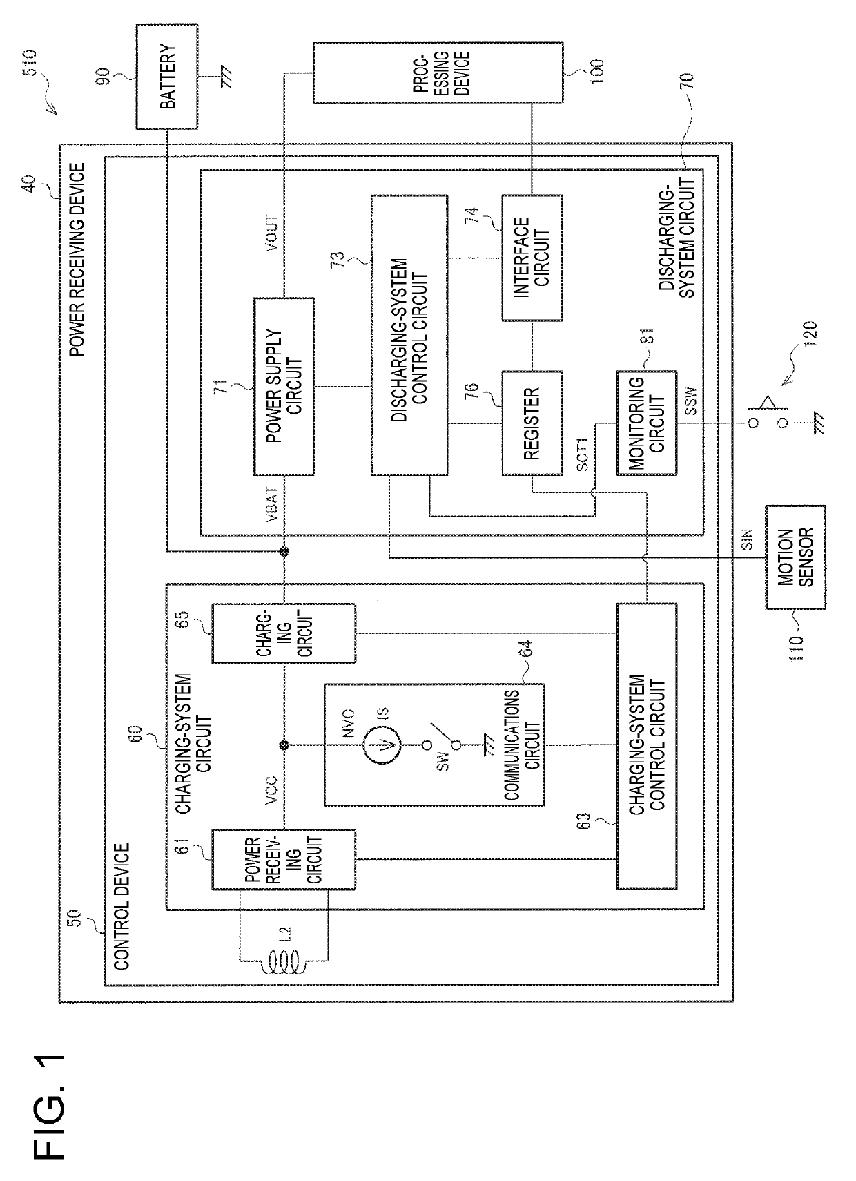
[0029]FIG. 1 shows a first configuration example of an electronic device 510 on a power receiving side, a power receiving device 40, and a control device 50 on the power receiving side, in a contactless power transmission system. Note that regarding operation of each part in contactless power transmission, only the main points will be explained here, and a detailed description will be given later. Following is mainly a description of power supply control performed by the power receiving device 40.

[0030]The electronic device 510 includes a battery 90 subject to charging, the power receivin...


PUM


Abstract

The control device includes a charging-system circuit and a discharging-system circuit. The discharging-system circuit has a discharging-system control circuit, and a power supply circuit that performs power supply to a processing device. The discharging-system control circuit performs a first control that, when the power supply is in an off state, when motion of the power receiving device is detected by a motion sensor, switches the power supply to an on state based on a detection signal from the motion sensor, and a second control that switches the power supply between the on state on the off state based on a control signal. The discharging-system control circuit, in the first control, disables the second control when motion of the power receiving device has been detected by the motion sensor.

Description

CROSS REFERENCE[0001]This application claims benefit of Japanese Application JP 2018-064296, filed on Mar. 29, 2018. The disclosure of the prior application is hereby incorporated by reference herein in its entirety.BACKGROUND1. Technical Field[0002]The present invention relates to a control device, a power receiving device, an electronic device, and the like.2. Related Art[0003]An acceleration sensor, a gyro sensor, and the like are known as motion sensors that detect a motion applied to the sensor. For example, a motion sensor is incorporated into an electronic device, and control of the electronic device is performed based on a detection signal from the motion sensor. For example, JP-A-2014-42213 discloses a hearing aid device including a motion sensor that detects an operation of a hearing aid device or an accessory of the hearing aid device, and a control unit that executes repeat playback when a predetermined operation has been detected by the motion sensor.[0004]Also, in rece...

Claims


Application Information

Patent Timeline
Patent Type & Authority Applications(United States)
IPC IPC(8): H02J50/10H02J7/02
CPCH04R25/554H02J7/025H02J50/10H04R2225/31H01H47/002
Inventor ONISHI, KOTA
Owner SEIKO EPSON CORP
Why Eureka
Try Eureka