System for controlling exterior vehicle lights

Inactive Publication Date: 2005-08-09
GENTEX CORP
View PDF72 Cites 262 Cited by
  • Summary
  • Abstract
  • Description
  • Claims
  • Application Information

AI Technical Summary

Benefits of technology

[0009]According to one aspect of the present invention, a control system is provided to control exterior lights of a controlled vehicle. The control system comprises an imaging system configured to image the scene forward of the controlled vehicle, and a control circuit for processing the image of

Problems solved by technology

Some systems that effectively detect headlamps are unable to adequately detect tail lights.
Most prior systems are unable to distinguish nuisance light sources, such as reflectors, street signs, streetlights, house lights, or the like, from light sources that require headlight control.
Accordingly, these systems are subject to undesirable dimming of the high beams when no other traffic is present and turning on the high beams

Method used


Image

  • System for controlling exterior vehicle lights
  • System for controlling exterior vehicle lights
  • System for controlling exterior vehicle lights

Examples


Example

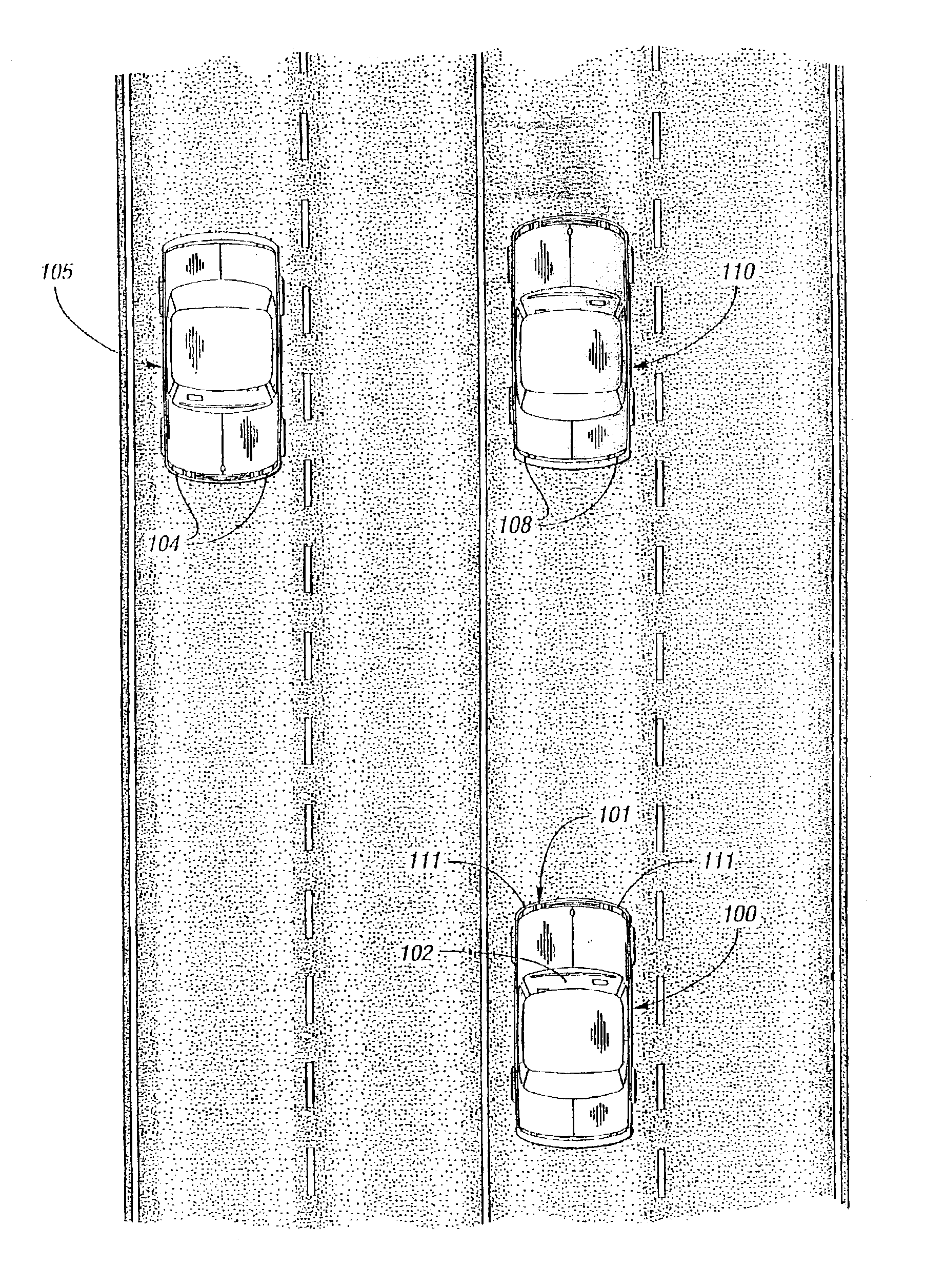
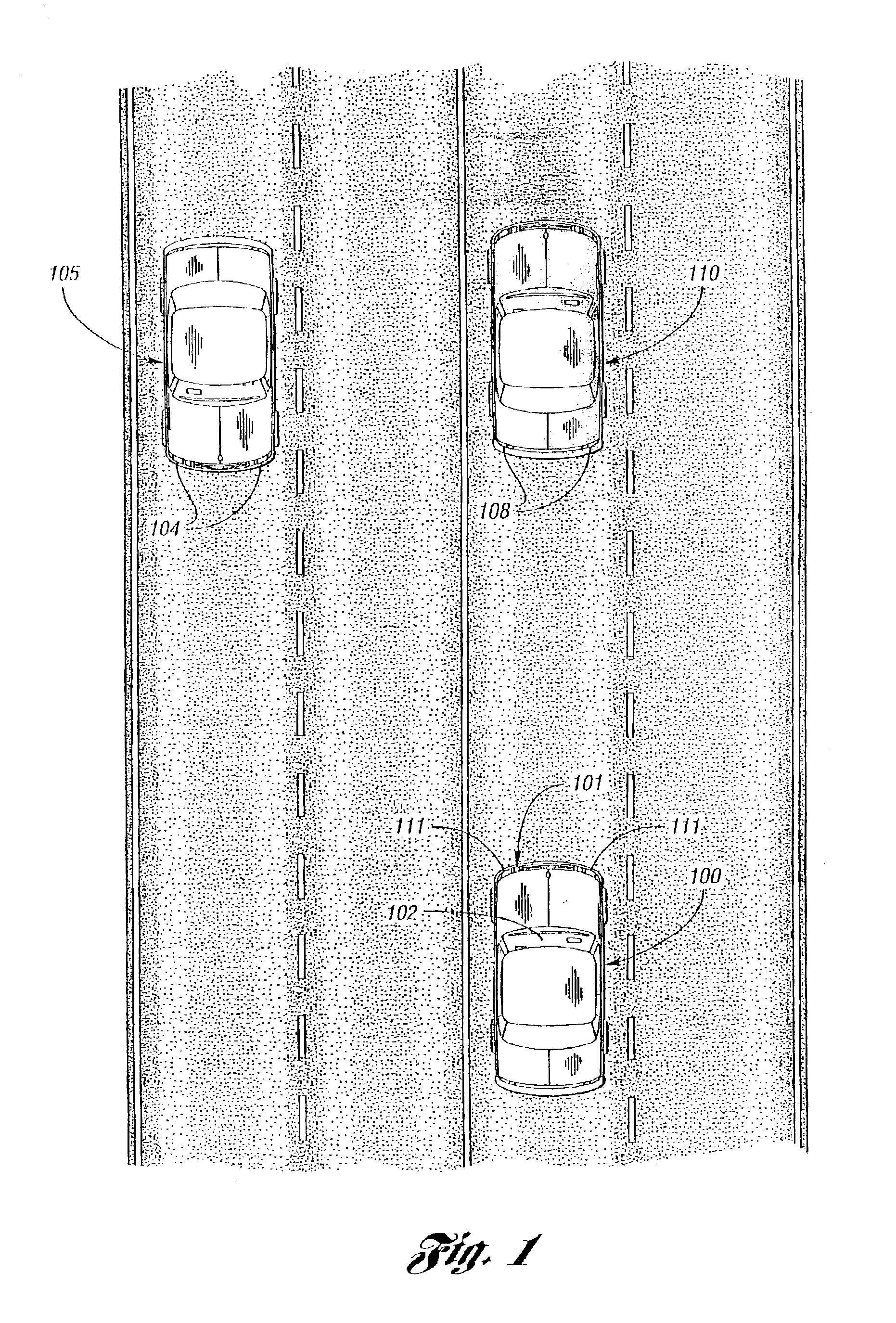
[0081]The present invention generally pertains to a control system for controlling the exterior lights of a vehicle. As noted above, such exterior lights may include headlamps, tail lights, foul weather lights such as fog lights, brake lights, center-mounted stop lights (CHMSLs), turn signals, back-up lights, cargo lights, puddle lights, license plate illuminators, etc. The headlamps may be operated in several different modes including conventional low-beam and high-beam states. They may also be operated as daytime running lights, and additionally as super-bright high beams in those countries where they are permitted. The headlamp brightness may also be continuously varied between the low, high, and super-high states. Separate lights may be provided for obtaining each of these headlamp states or the actual brightness of the headlamps may be varied to provide these different headlamp states. In either case, the “perceived brightness” of the headlamps is varied. As used herein, the te...


PUM


Abstract

A system and method of automatically controlling exterior vehicle lights includes an image sensor and a controller to generate control signals. The control signals are derived based on information obtained from the image sensor as well as other detected parameters pertaining to the detected light source(s), the vehicle having the inventive control system, and the ambient environment. The control circuit may simply turn certain exterior lights on or off, or change the brightness, aim, focus, etc. to produce various beam patterns that maximize the illuminated area in front of the vehicle without causing excessive glare in the eyes of other drivers.

Description


Claims


Application Information

Patent Timeline
IPC IPC(8): B60Q1/08B60Q1/04B60Q1/14B60Q1/18G06V10/141
CPCB60Q1/085B60Q1/143B60Q1/18B60Q1/2603G06K9/00664G06K9/2027B60Q2300/054B60Q2300/056B60Q2300/112B60Q2300/114B60Q2300/116B60Q2300/122B60Q2300/134B60Q2300/142B60Q2300/144B60Q2300/21B60Q2300/312B60Q2300/314B60Q2300/32B60Q2300/322B60Q2300/331B60Q2300/332B60Q2300/3321B60Q2300/333B60Q2300/334B60Q2300/337B60Q2300/41B60Q2300/42B60Q2400/30G06V20/10G06V20/56G06V10/141B60Q1/14
Inventor STAM, JOSEPH S.BECHTEL, JON H.REESE, SPENCER D.ROBERTS, JOHN K.TONAR, WILLIAM L.POE, G. BRUCENEWHOUSE, DOUGLAS J.
Owner GENTEX CORP
Why Eureka
Try Eureka