Eureka AIR delivers breakthrough ideas for toughest innovation challenges, trusted by R&D personnel around the world.

Method for embedding electronics into a puck and puck having embedded electronics

a technology of electronics and pucks, applied in the field of pucks embedding electronics, can solve the problems of loss of function, high mechanical force of pucks, and high probability of damage to electronics, in particular batteries, and achieve the effect of improving the structural persistence of glued connections

Active Publication Date: 2019-10-10
KINEXON GMBH
View PDF9 Cites 2 Cited by
  • Summary
  • Abstract
  • Description
  • Claims
  • Application Information

AI Technical Summary

Benefits of technology

The present invention aims to protect electronics embedded in a puck from damage caused by mechanical stress. The invention achieves this through a carrier structure having a rigid shell and layers of differential stiffness. The first layer (a softer layer) absorbs the mechanical energy transferred to the puck, while the second layer (a harder layer) protects the susceptible structures inside the puck from deformation. The invention further includes circuitry that can switch between activating different transmitter circuits based on their proximity to the surface of the puck, improving the efficiency of transmission and reducing interference. Additionally, the invention includes a recess that improves the structural persistence of the glued connection.

Problems solved by technology

Hockey pucks experience immense mechanical forces when the puck is hit by a player's stick or impacts on a barrier.
When the mechanical forces are transferred to the electronics in the puck, the electronics, in particular the battery, is likely to be damaged quickly, risking a loss of function during game-play.
Hockey pucks embedding electronics according to the state of the art do not provide for an embedding that sufficiently protects electronics.
Yet, an embedding that is rigid also transfers all mechanical stress to the electronics, which quickly causes damage to the circuitry and fatigue of material.
A further problem is implied by the operating of transmitters close to an ice surface.
Thus, a transmitter transmitting close to an ice surface does not work efficiently, hampering the reception of the signal of the puck.
The transmitter circuit near the planar surface of the puck currently facing downwards is closer to the ice surface and, thus, cannot transmit efficiently.

Method used


Image

  • Method for embedding electronics into a puck and puck having embedded electronics
  • Method for embedding electronics into a puck and puck having embedded electronics
  • Method for embedding electronics into a puck and puck having embedded electronics

Examples


Embodiment Construction

[0027]A puck containing a transmitter circuit and a method of producing the puck will be described in detail in the following. For purposes of explanation, examples and specific details are set forth in order to provide a thorough understanding of the embodiments of the present invention. Embodiments as defined by the claims may include some or all of the features in these examples alone or in combination with other features described below and may further include modifications and equivalents of the features and concepts described herein. The following description will refer to FIGS. 1 to 5 explaining embodiments of the present invention in detail.

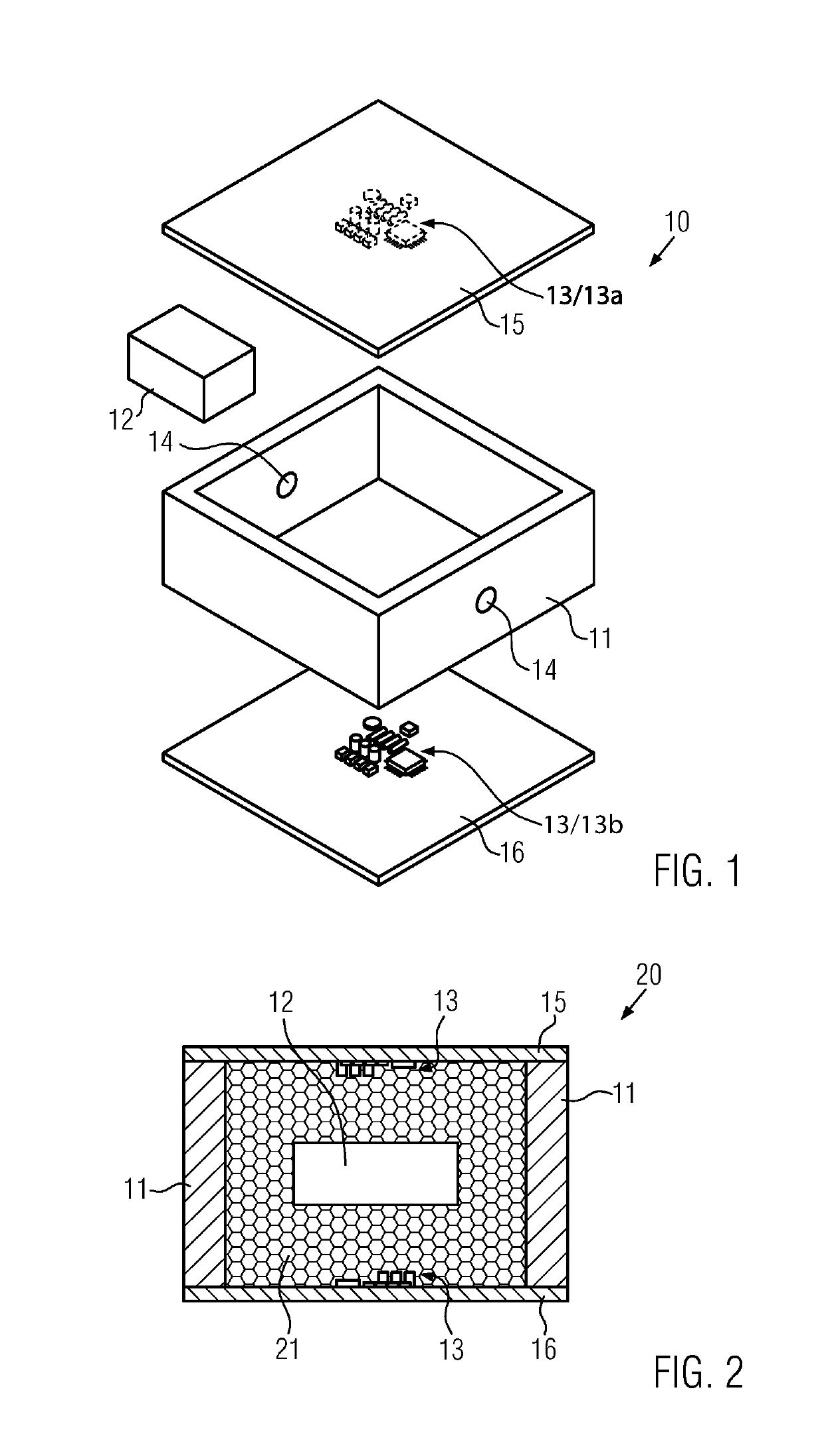
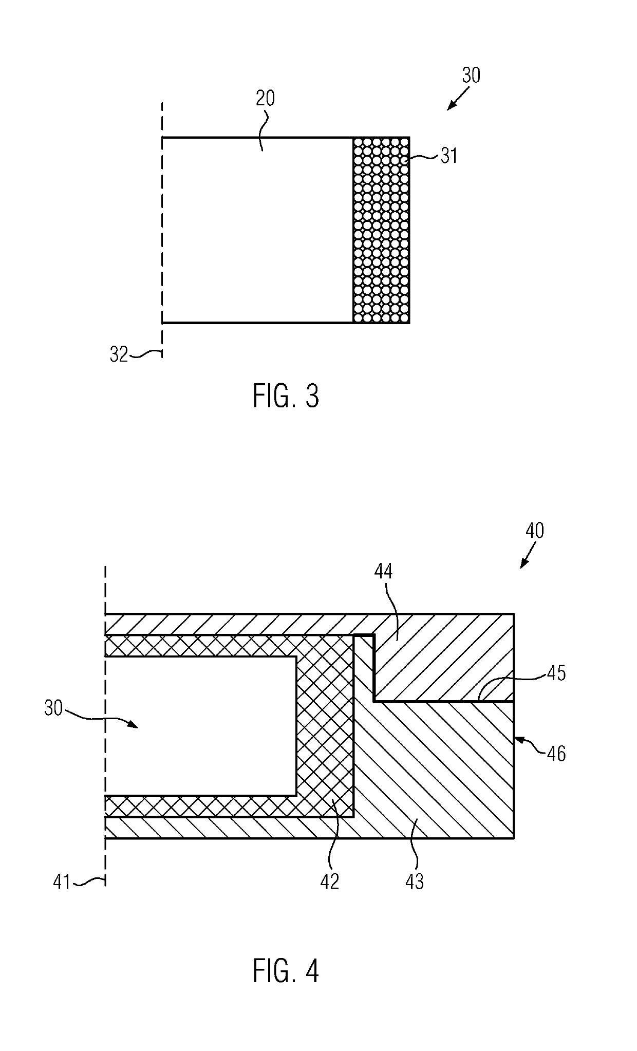
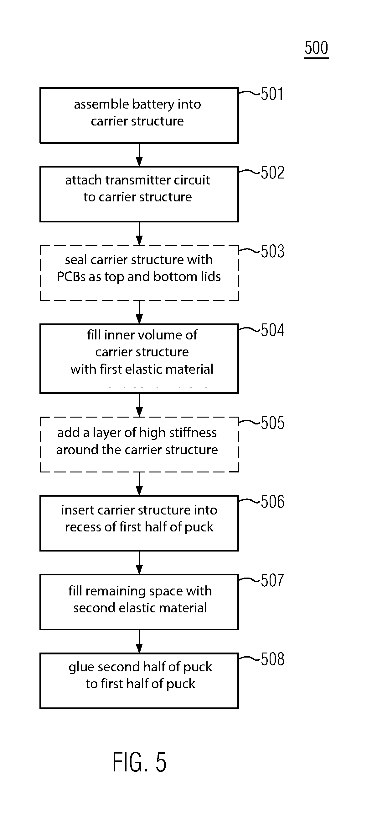
[0028]FIG. 1 shows an exploded view of components positioned within a puck according to embodiments of the invention. FIG. 1 shows a carrier structure 11 having a rigid shell. In an embodiment, the carrier structure 11 may be 3D printed. A battery 12, which may be a primary cell or a rechargeable battery, is located within the carrier str...


PUM


Abstract

A puck embedding at least one transmitter circuit, and a method for producing a puck embedding at least one transmitter circuit. To protect the electronics from displacement or damage, the puck employs a layered structure. The puck has a centrally located cavity, containing a carrier structure having a rigid shell, at least one transmitter circuit supported by the carrier structure, and a battery provided within the carrier structure. The battery is embedded in a first elastic material provided within the carrier structure. The carrier structure is embedded in a second elastic material provided within the centrally located cavity.

Description

CROSS RELATED APPLICATIONS[0001]This application claims the benefit of the priority of European Patent Application No. 18161049.4, filed Mar. 9, 2018, and herein incorporated by reference in its entirety, where such incorporation is permitted.FIELD OF THE INVENTION[0002]The present invention relates to a puck embedding electronics, specifically a radio transmitter, in a way that prevents damage to the electronics when the puck experiences mechanical stress.BACKGROUND OF THE INVENTION[0003]A ball or a puck equipped with an electronic tag allows tracking of its position during a ball game. Electronic tracking of the position can support referees in overseeing the game, provide insights for trainers aiming to improve the game-play of a team, or provide an augmented experience for spectators. Ice hockey pucks, specifically, are small and fast moving objects particularly difficult to track by naked eye, enhancing the relative benefit provided by electronic tracking of the puck.[0004]Ball...

Claims


Application Information

Patent Timeline
IPC IPC(8): A63B43/00A63B24/00
CPCA63B43/002A63B2225/54A63B24/0021A63B43/00A63B45/00A63B67/14A63B69/0024A63B2102/24A63B2209/02A63B2220/13A63B2220/18A63B2220/30A63B2220/40A63B2220/53A63B2220/80A63B2220/833A63B2225/50
Inventor HOLZNER, SIMONBOHN, BERNHARD JOHANN
Owner KINEXON GMBH
Why Eureka
Eureka Blog
Learn More