Fuel injectors for turbomachines having inner air swirling

a turbomachine and fuel injector technology, applied in the field of turbomachines, can solve problems such as affecting performan

Active Publication Date: 2019-10-10
COLLINS ENGINE NOZZLES INC
View PDF17 Cites 5 Cited by
  • Summary
  • Abstract
  • Description
  • Claims
  • Application Information

AI Technical Summary

Benefits of technology

[0006]The upstream extending wall can include one or more inner swirling holes configured to effuse swirling air. The upstream extending wall can extend axially upstream beyond the angled or curved wall and into a constant inner diameter area of the heat shield. An outer surface of the heat shield can include an engagement protrusion axially upstream from the air swirler and configured to engage with the fuel distributor to seat the air swirler proximate an outlet of the fuel distributor.

Problems solved by technology

These parts of traditional injectors are difficult to attach and may experience inadvertent release of the swirler which can affect performance.

Method used


Image

  • Fuel injectors for turbomachines having inner air swirling
  • Fuel injectors for turbomachines having inner air swirling
  • Fuel injectors for turbomachines having inner air swirling

Examples


Embodiment Construction

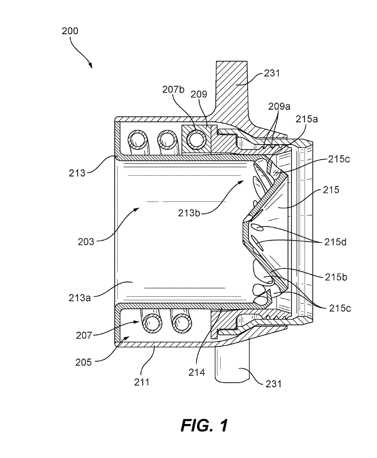
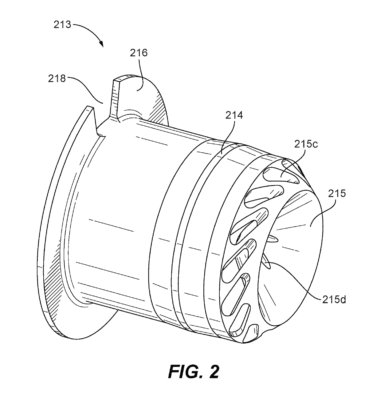
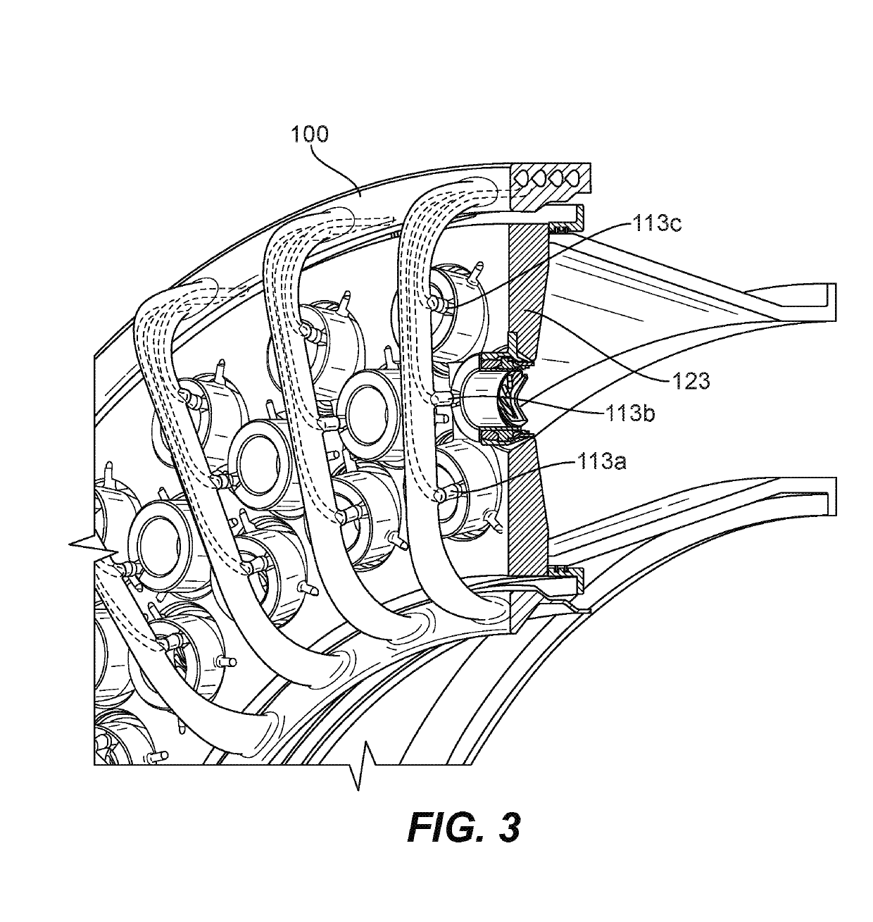
[0013]Reference will now be made to the drawings wherein like reference numerals identify similar structural features or aspects of the subject disclosure. For purposes of explanation and illustration, and not limitation, an illustrative view of an embodiment of a fuel injector (which can also be referred to as a fuel nozzle) in accordance with the disclosure is shown in FIG. 1 and is designated generally by reference character 200. Other embodiments and / or aspects of this disclosure are shown in FIGS. 2-3.

[0014]Referring to FIGS. 1 and 2, a fuel injector 200 for a turbomachine includes an inner heat shield 213 having an air cavity wall 213a defining an air cavity 203 for allowing air to flow therethrough. The inner heat shield 213 includes an integral air swirler 215 forming a downstream end 213b of the heat shield 213 as shown. The fuel injector 200 can include an outer heat shield 211 and a fuel distributor 209.

[0015]The integral air swirler 215 can extend in an axially downstrea...


PUM


Abstract

A fuel injector for a turbomachine includes an inner heat shield having an air cavity wall defining an air cavity for allowing air to flow therethrough. The inner heat shield includes an integral air swirler forming a downstream end thereof. The integral air swirler extends in an axially downstream direction at least as far as a fuel distribution channel defined on or in a fuel distributor of the injector to direct airflow at an outlet of the fuel distributor.

Description

BACKGROUND1. Field[0001]The present disclosure relates to turbomachines, more specifically to fuel injector systems for turbomachines.2. Description of Related Art[0002]A conventional fuel nozzle air swirler is comprised of a separate air swirler and heat shield element. These parts of traditional injectors are difficult to attach and may experience inadvertent release of the swirler which can affect performance. Such conventional methods and systems have generally been considered satisfactory for their intended purpose. However, there is still a need in the art for improved fuel nozzle / injector systems. The present disclosure provides a solution for this need.SUMMARY[0003]A fuel injector for a turbomachine includes an inner heat shield having an air cavity wall defining an air cavity for allowing air to flow therethrough. The inner heat shield includes an integral air swirler forming a downstream end thereof. The integral air swirler extends in an axially downstream direction at le...

Claims


Application Information

Patent Timeline
Patent Type & Authority Applications(United States)
IPC IPC(8): F23R3/28F02C7/18
CPCF23R3/283F02C7/18F23D2202/00F23D2206/10F23R3/12F23C2900/07001F23D11/383F23D14/24F23D2900/14021F23R3/14F23R3/286
Inventor PROCIW, LEV ALEXANDERRYON, JASON A.ZINK, GREGORY A.
Owner COLLINS ENGINE NOZZLES INC
Why Eureka
Try Eureka