Fuel control device, combustor, gas turbine, control method, and program

a technology of fuel control device and combustor, which is applied in the direction of machines/engines, mechanical equipment, lighting and heating apparatus, etc., can solve the problems of combustion vibration in the combustor of a gas turbine, and achieve the effect of improving the efficiency of the combustion process

Active Publication Date: 2016-11-10
MITSUBISHI HEAVY IND LTD
View PDF9 Cites 26 Cited by
  • Summary
  • Abstract
  • Description
  • Claims
  • Application Information

AI Technical Summary

Benefits of technology

[0019]According to the fuel control device, the combustor, the gas turbine, the control method, and the program described above, it is possible to suppress a deviation between a target fuel system fuel ratio for the turbine inlet temperature and an actual fuel system fuel ratio even in a transient period of a load change.

Problems solved by technology

Further, combustion vibration has been known to occur in a combustor of a gas turbine, for example, if a distribution ratio of fuel supplied from a plurality of systems is changed.

Method used


Image

  • Fuel control device, combustor, gas turbine, control method, and program
  • Fuel control device, combustor, gas turbine, control method, and program
  • Fuel control device, combustor, gas turbine, control method, and program

Examples


first embodiment

[0035]Hereinafter, a fuel control device according to a first embodiment of the present invention will be described with reference to FIGS. 1 to 5.

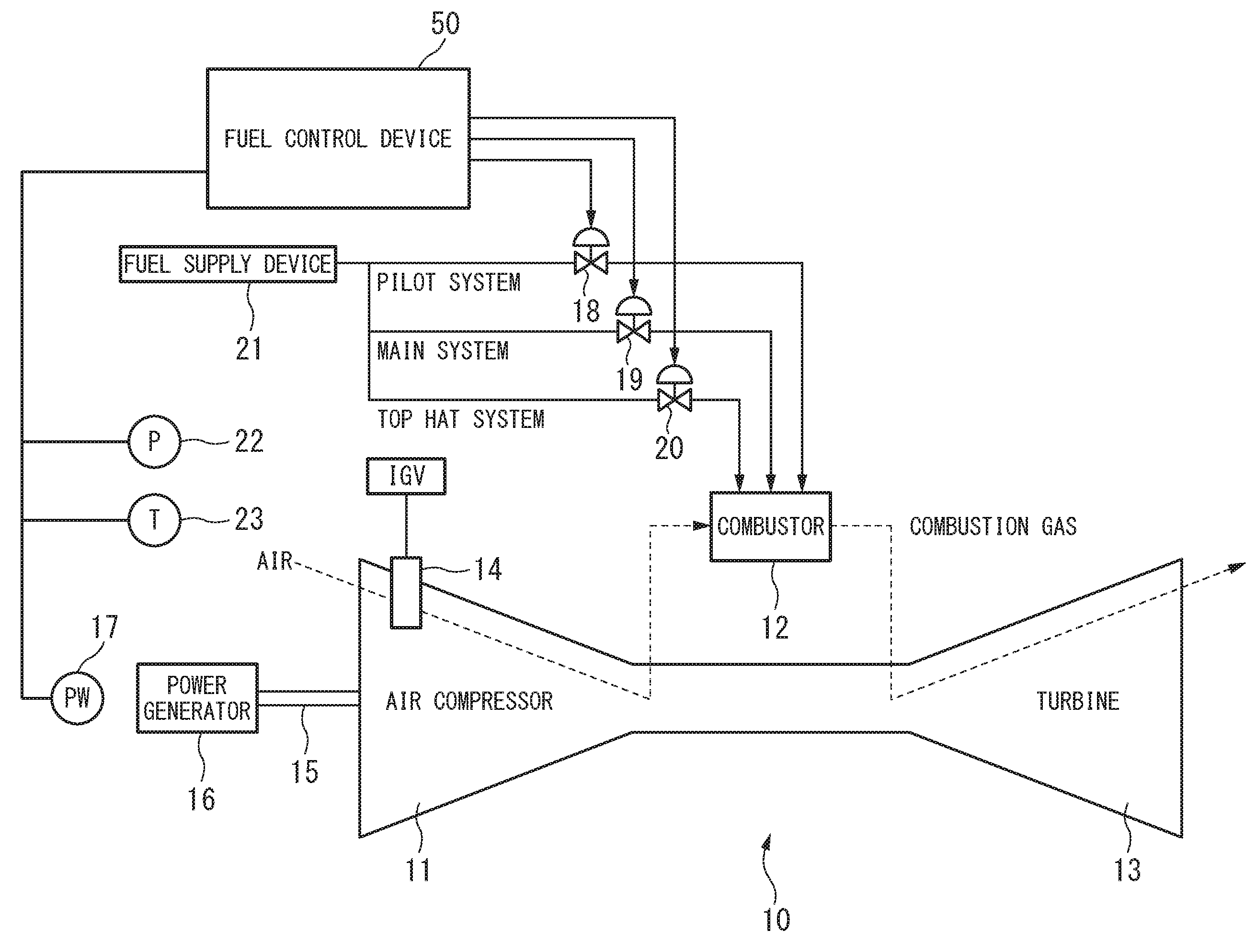
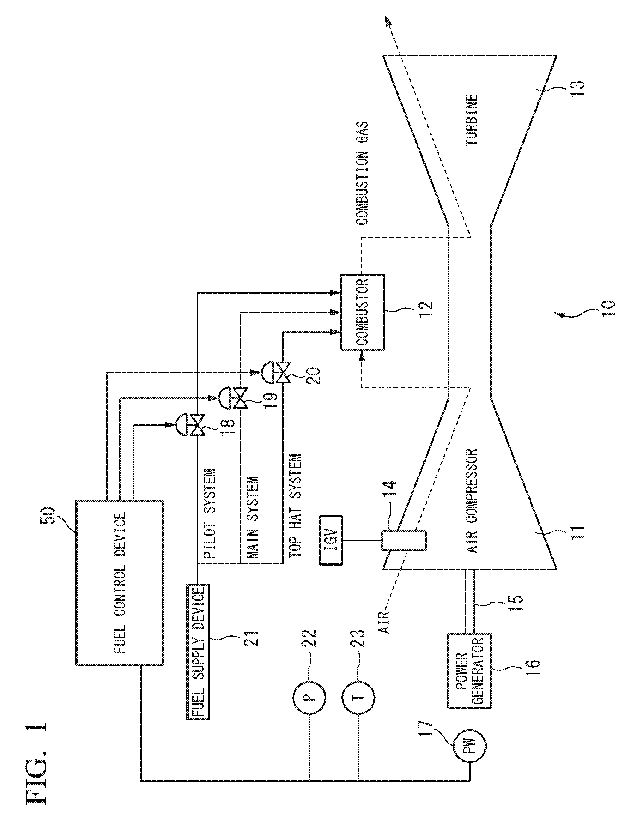
[0036]FIG. 1 is a system diagram of a gas turbine plant in this embodiment.

[0037]The gas turbine plant of this embodiment includes a gas turbine 10, a power generator 16 that generates power through driving of the gas turbine 10, and a fuel control device 50 that controls a behavior of the gas turbine 10, as illustrated in FIG. 1. The gas turbine 10 and the power generator 16 are coupled to each other by a rotor 15.

[0038]The gas turbine 10 includes an air compressor 11 that compresses air to generate compressed air, a combustor 12 that mixes the compressed air with a fuel gas, burns the gas, and generates a combustion gas at a high temperature, and a turbine 13 that is driven by the combustion gas.

[0039]An IGV 14 is provided in the air compressor 11. The IGV 14 adjusts a flow of air into the air compressor 11. A pressure gauge 22 and a th...

second embodiment

[0064]Hereinafter, a fuel control device according to a second embodiment of the present invention will be described with reference to FIGS. 6 and 7.

[0065]FIG. 6 is a block diagram illustrating an example of a fuel control device of this embodiment.

[0066]As illustrated in FIG. 6, a fuel control device 50 in this embodiment includes a gas turbine output correction amount calculation unit 56. Further, a method of calculating an expected output value of the gas turbine in the gas turbine output prediction value calculation unit 51 is different from that in the first embodiment. Other configurations are the same as in the first embodiment.

[0067]The gas turbine output correction amount calculation unit 56 acquires a CSO from the gas turbine output control unit and calculates a correction amount for the output value of the gas turbine on the basis of the CSO. For the calculation of the gas turbine output value correction amount, a table in which the CSO and the gas turbine output value co...

third embodiment

[0076]Hereinafter, a fuel control device according to a third embodiment of the present invention will be described with reference to FIGS. 8 and 9.

[0077]FIG. 8 is a block diagram illustrating an example of a fuel control device of this embodiment.

[0078]As illustrated in FIG. 8, a fuel control device 50 in this embodiment includes a load change rate calculation unit 57 and a coefficient calculation unit 58. Other configurations are the same as those in the second embodiment.

[0079]The load change rate calculation unit 57 acquires an output measurement value of the power generator 16 from the power meter 17. The load change rate calculation unit 57 calculates a change in load per unit time.

[0080]The coefficient calculation unit 58 acquires a weighting coefficient for the gas turbine output correction amount according to the load change rate calculated by the load change rate calculation unit 57. For the calculation of the weighting coefficient, a table or a function in which the load ...


PUM


Abstract

A fuel control device includes a combustion temperature estimation value calculation unit that calculates a temperature estimation value when a mixture of fuel and inflow air is burned using an atmospheric condition, an opening degree command value of a valve that controls the amount of air that is mixed with the fuel and burned, and an output prediction value calculated on the basis of a fuel control signal command value used for calculation of a total fuel flow rate flowing through a plurality of fuel supply systems, a fuel distribution command value calculation unit that calculates a fuel distribution command value indicating a distribution of fuel output from the fuel supply systems based on the temperature estimation value, and outputs the fuel distribution command value, and a valve opening degree calculation unit that calculates each valve opening degree of a fuel flow rate control valve of the fuel supply systems.

Description

TECHNICAL FIELD[0001]The present invention relates to a fuel control device, a combustor, a gas turbine, a control method, and a program.[0002]Priority is claimed on Japanese Patent Application No. 2014-034871, filed Feb. 26, 2014, the content of which is incorporated herein by reference.BACKGROUND ART[0003]In supply of fuel to a combustor of a gas turbine, the fuel is divided and supplied to a plurality of systems in terms of efficiency or stability of combustion in some cases. In such cases, it is necessary to consider distribution of the fuel to the respective systems.[0004]FIG. 14 is a diagram illustrating an example of a fuel distribution control of a gas turbine of the related art. As illustrated in FIG. 14, the fuel control device of the related art estimates a temperature of a combustion gas at an inlet of the turbine on the basis of an atmospheric pressure, an atmospheric temperature, an inlet guide vane (IGV) opening degree designation value, and a gas turbine output value...

Claims


Application Information

Patent Timeline
Patent Type & Authority Applications(United States)
IPC IPC(8): F02C9/28F02C9/26F23R3/28
CPCF02C9/28F23R3/28F05D2240/12F05D2270/301F05D2270/303F02C9/263F05D2270/44F23N1/002F23N5/242F23R2900/00013F23N2225/20F23N2241/20F02C7/228F02C9/26F02C9/50
Inventor YAMAMOTO, KEISUKESONODA, TAKASHISAITOFUJII, FUMINORINAKAHARA, HISASHIHAGA, RYOICHITAKENAKA, RYUJIIWASAKI, YOSHIFUMIAKIZUKI, WATARUMATSUMI, ISAMUSUMIMURA, NAOHIROYOSHIOKA, SHINICHI
Owner MITSUBISHI HEAVY IND LTD
Why Eureka
Try Eureka