
Fuel mixer apparatus and method

a fuel mixer and mixer technology, applied in mechanical equipment, machines/engines, engine components, etc., can solve the problems of general neglect of the intake system of medium and heavy duty engines, limited performance of carburetors, and inability to provide fuel to the engin

Active Publication Date: 2008-09-23
OMNITEK ENG
View PDF19 Cites 26 Cited by
  • Summary
  • Abstract
  • Description
  • Claims
  • Application Information

AI Technical Summary

Problems solved by technology

However, there are several common problems exhibited by internal combustion engines that tend to disturb the AFR.
Intake system development is extensive for automotive engines utilizing multipoint injection, but intake systems on medium and heavy duty engines are generally neglected.
On the fuel side of the equation, carburetors have provided limited performance and can meet older emission standards, however it should be noted that no carbureted engines are currently sold in the United States, as they simply will not pass current emission standards.
Again, this type of a system has difficulty meeting current emissions levels.
Unfortunately, the multipoint system which has worked so well for gasoline engines is not a good solution for a diesel engine converted to natural gas.

Method used


Image

  • Fuel mixer apparatus and method
  • Fuel mixer apparatus and method
  • Fuel mixer apparatus and method

Examples


Embodiment Construction

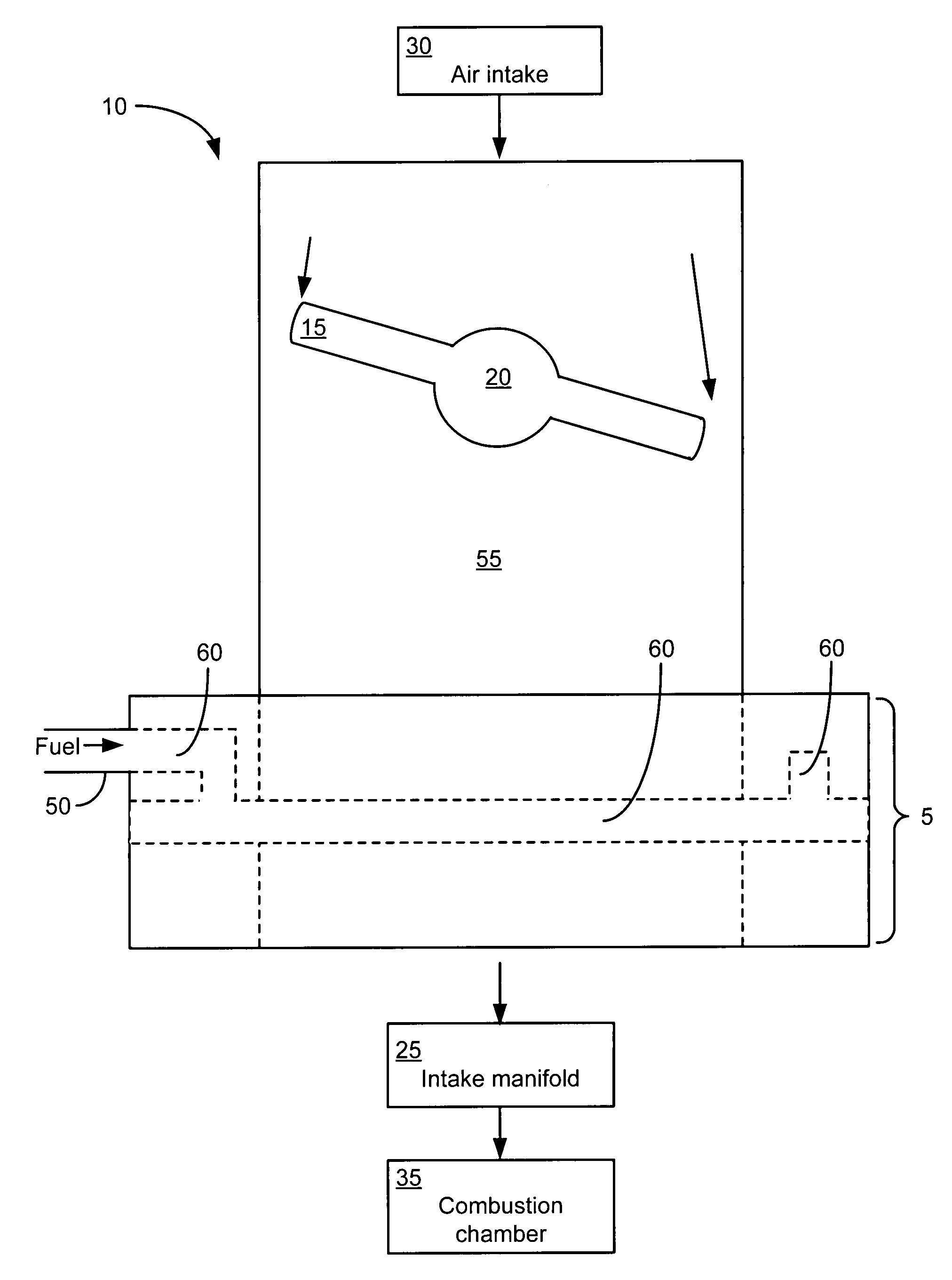
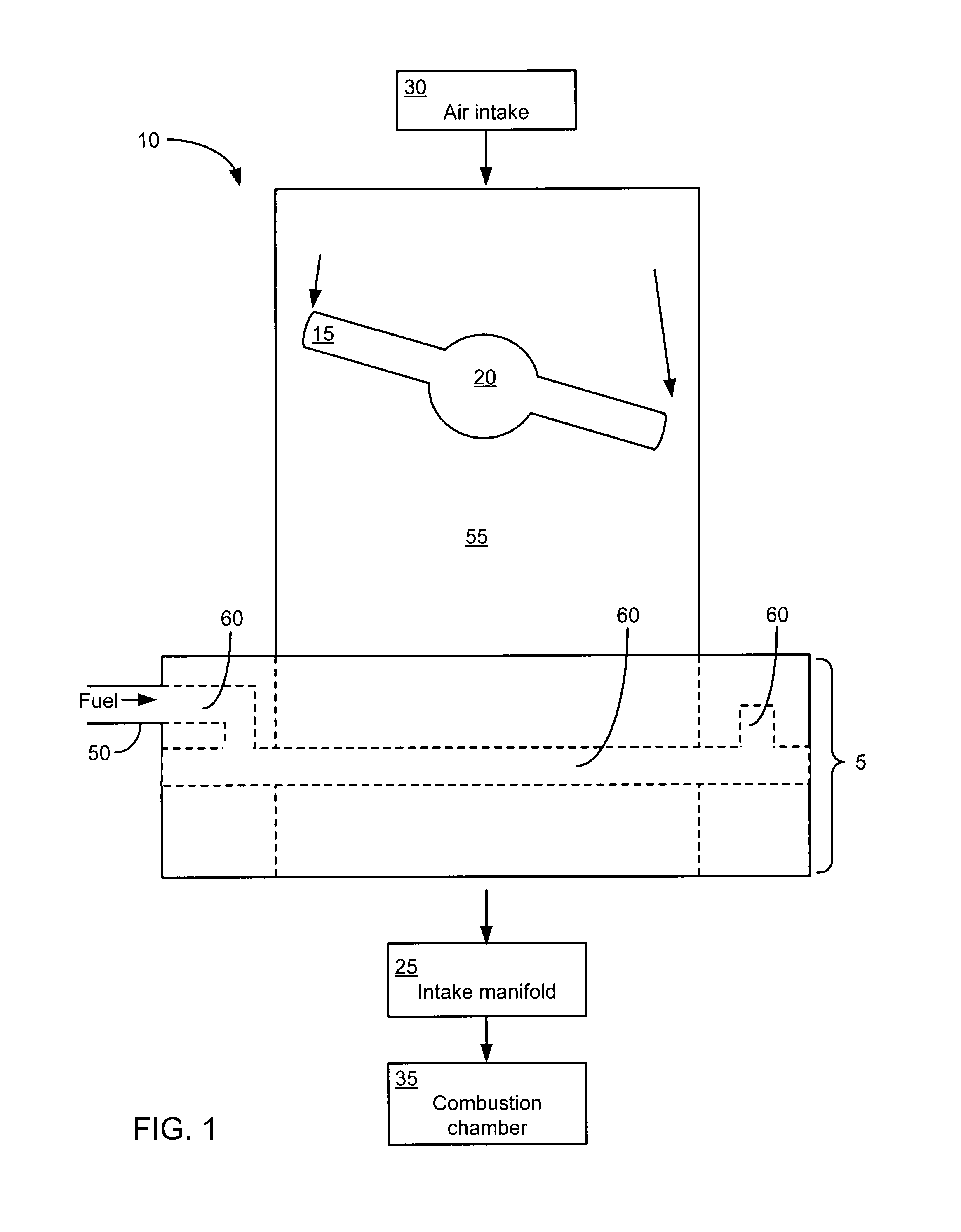
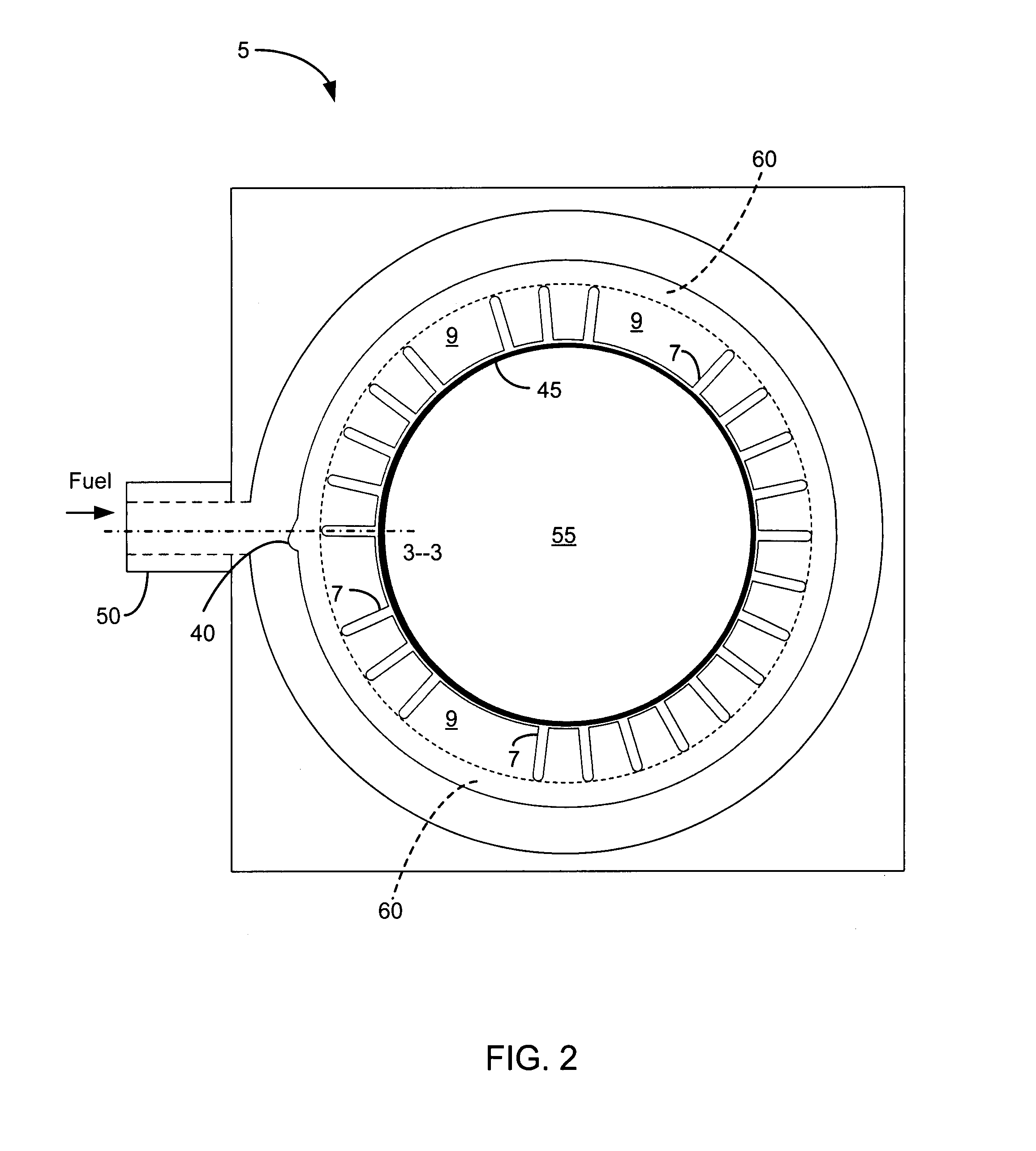
[0013]In the following paragraphs, the fuel mixer will be described in detail by way of example with reference to the attached drawings. While the fuel mixer is capable of embodiment in many different forms, there is shown in the drawings and will herein be described in detail specific embodiments, with the understanding that the present disclosure is to be considered as an example of the principles of the fuel mixer and not intended to limit the invention to the specific embodiments shown and described. That is, throughout this description, the embodiments and examples shown should be considered as exemplars, rather than as limitations on the fuel mixer. As used herein, the “fuel mixer” to any one of the embodiments of the invention described herein, and any equivalents. Furthermore, reference to various feature(s) of the “fuel mixer” throughout this document does not mean that all claimed embodiments or methods must include the referenced feature(s).

[0014]Specific embodiments of t...


PUM


Abstract

An apparatus to deliver a fuel into a chamber is provided. In one embodiment, the apparatus includes a fuel inlet and a substantially circular fuel distribution canal communicating with the fuel inlet. A biasing element is coupled to the substantially circular fuel distribution canal, with the biasing element having a plurality of slots arranged to non-uniformly dispense the fuel into the chamber. Another embodiment includes a flange positioned in the substantially circular fuel canal, with the flange structured to perturb a fuel passing into the chamber. This Abstract is provided for the sole purpose of complying with the Abstract requirement rules that allow a reader to quickly ascertain the subject matter of the disclosure contained herein. This Abstract is submitted with the explicit understanding that it will not be used to interpret or to limit the scope or the meaning of the claims.

Description

FIELD OF THE INVENTION[0001]The present invention generally relates to internal combustion engines. More particularly, the invention concerns a method and apparatus to mix air and fuel in an internal combustion engine.BACKGROUND OF THE INVENTION[0002]Spark ignition engines that employ single or multipoint fuel metering concepts rely upon a throttle body to proportion the air flow rate in response to the operators commanded power level. Simply put, the more air flow allowed into the engine, the higher the power output. For most engines, the operator commands power via the foot pedal which either directly moves the throttle plate through an intermediate cable, or indirectly with a drive-by-wire throttle. In either case, the fuel management system adds the correct amount of fuel as required by the commanded airflow to achieve a desired air-to-fuel ratio (AFR).[0003]As an engine is driven though different speeds and loads, the fuel management system calculates and delivers the ideal amo...

Claims


Application Information

Patent Timeline
IPC IPC(8): F02B43/02F02B43/00
CPCF02M19/0228
Inventor PETERSEN, PETER
Owner OMNITEK ENG
Learn More