Turbine fuel ring assembly

a technology of fuel ring and turbine engine, which is applied in the direction of machines/engines, combustion types, lighting and heating apparatus, etc., can solve the problems of limiting the amount of nox emitted by turbine engines and difficult to integrate it into more recent turbine engine designs

Active Publication Date: 2005-02-24
SIEMENS ENERGY INC
View PDF12 Cites 29 Cited by
  • Summary
  • Abstract
  • Description
  • Claims
  • Application Information

AI Technical Summary

Problems solved by technology

Environmental regulations may limit the amount of NOx emitted from turbine engines.
While the above-described prior fuel ring configuration has proved successful in combination with certain turbine engine designs, it has been difficult to integrate it into more recent turbine engine designs because of structural interferences with nearby components.

Method used


Image

  • Turbine fuel ring assembly
  • Turbine fuel ring assembly
  • Turbine fuel ring assembly

Examples


Embodiment Construction

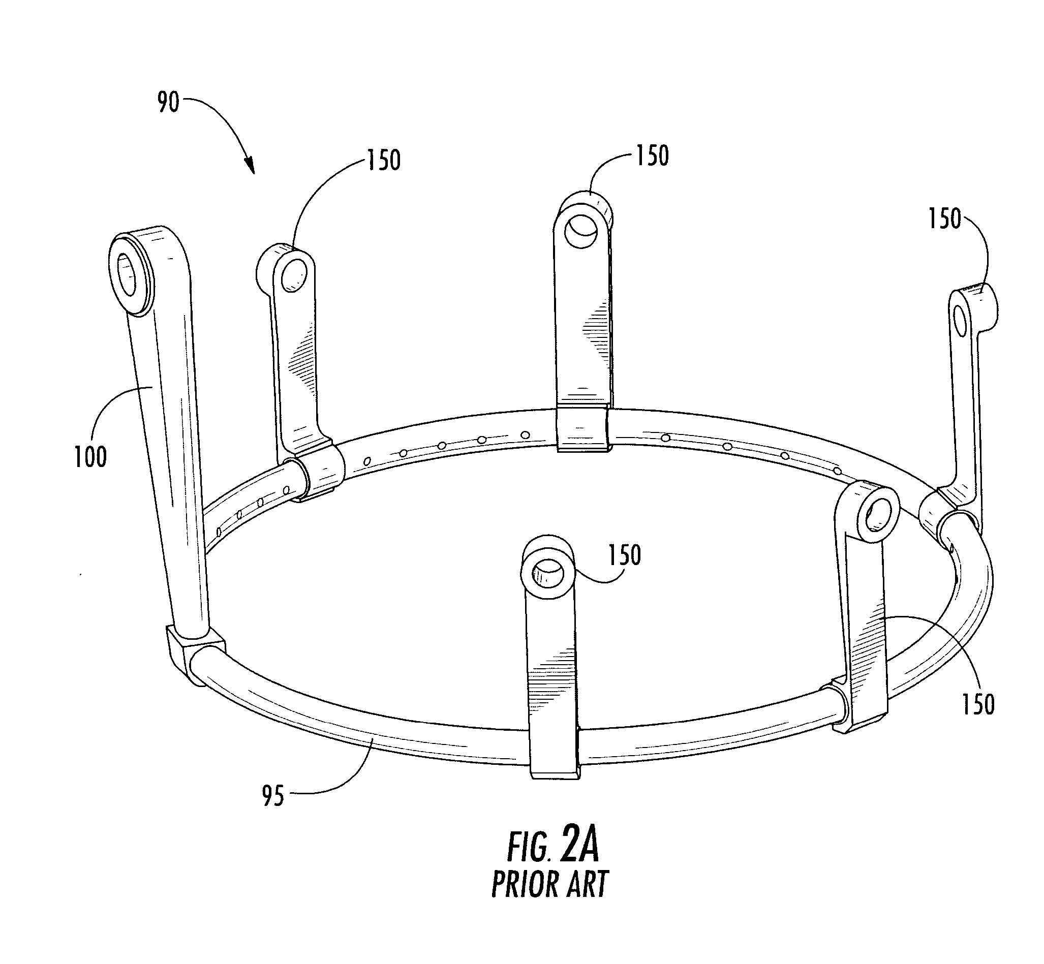
[0036] Aspects of the present invention improve upon the prior fuel ring configuration. Aspects of the present invention relate to a fuel ring assembly that can avoid interferences problems with surrounding components. Other aspects of the present invention are directed to novel geometries for the attachment legs and the fluid supply tube that facilitate installation and / or provide improved stress distribution characteristics.

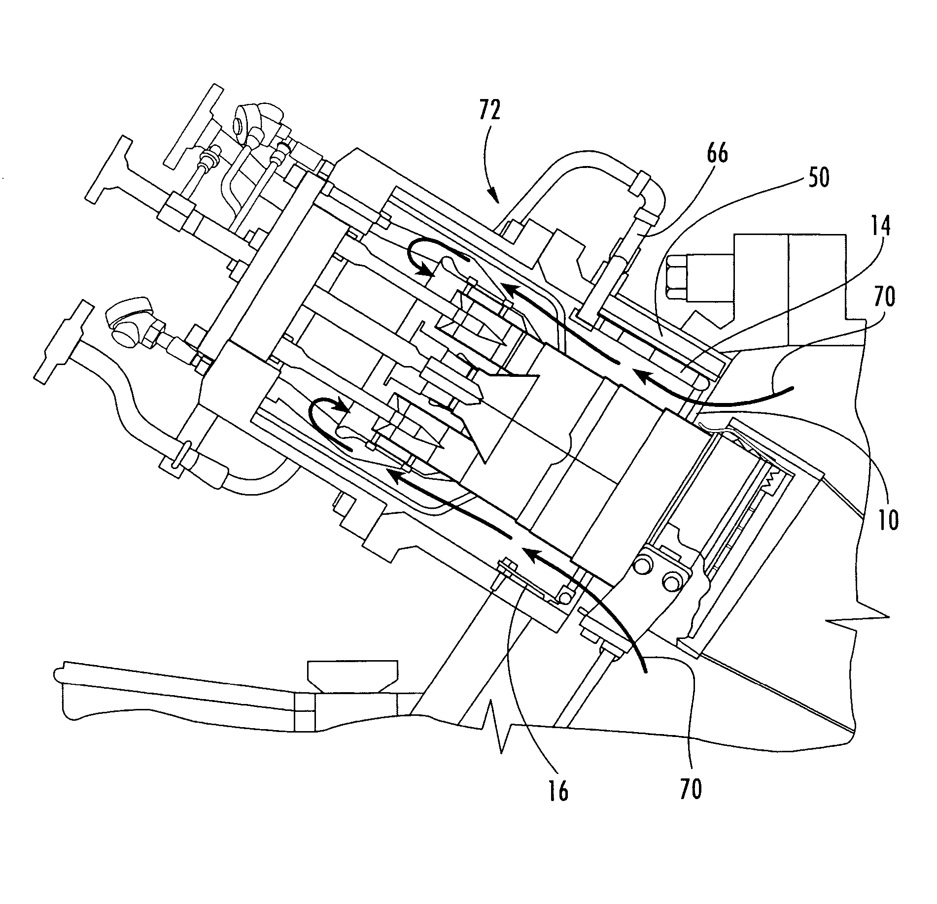
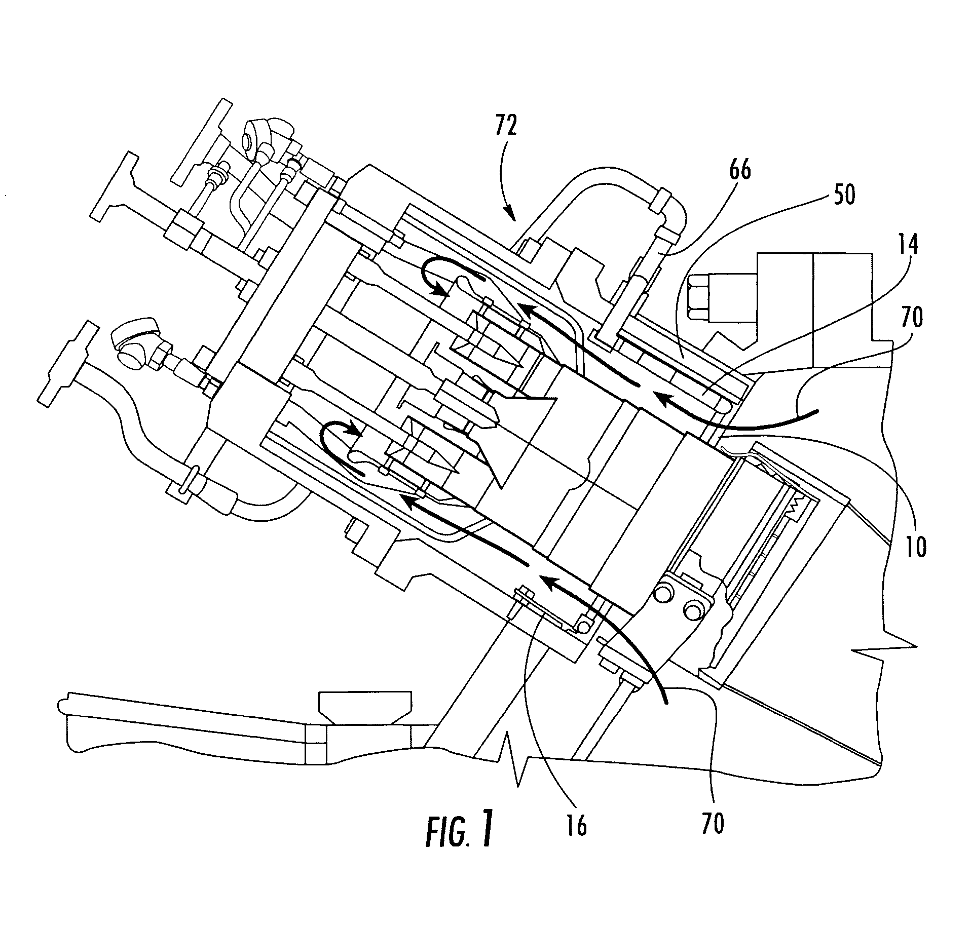
[0037] Embodiments of the invention will be explained in the context of a turbine fuel ring assembly, but the detailed description is intended only as exemplary. Embodiments of the invention are shown in FIGS. 1, 2B, 4 and 6-8, but the present invention is not limited to the illustrated structure or application.

[0038] As shown in FIG. 2B, aspects of the present invention relate to a turbine fuel ring assembly 10. The assembly generally comprises a fuel ring 12, one or more fluid supply tubes 14 and one or more attachment legs 16. Each of these components will...


PUM


Abstract

A turbine fuel ring assembly includes a fuel distribution ring, at least one fuel supply tube attached to the fuel distribution ring and at least one attachment leg connected to the fuel distribution ring. The fuel ring has a hollow interior and a plurality of apertures for expelling a fluid. The attachment leg is configured to allow flexibility due to thermal expansion induced under certain load conditions such as during engine start-up or shut-down. Further, the configuration of the attachment legs provides improved stress distribution characteristics. The fuel supply tube includes a rectangular passage and a round passage that are disposed substantially transverse to each other and in fluid communication with each other and with the hollow interior of the fuel distribution ring. The rectangular passage and the round passage have substantially identical cross-sectional areas. The fuel supply tube is configured to avoid structural interferences with neighboring components.

Description

FIELD OF THE INVENTION [0001] The invention relates in general to turbine engines and, more particularly, to a turbine fuel ring assembly configured to avoid structural interferences with neighboring components and to provide enhanced stress distribution characteristics. BACKGROUND OF THE INVENTION [0002] Environmental regulations may limit the amount of NOx emitted from turbine engines. One known manner for reducing NOx emissions is to mix the compressed air used for combustion with fuel before the air enters the primary combustion zone. Such premixed air burns cleaner than combustion air that is not premixed so as to reduce the amount of NOx generated. In addition to the NOx reduction benefit, premixed combustion air can assist in the management of the dynamic forces during combustion. In particular, when the primary combustion zone is provided with a air / fuel premixture, a more stable, controlled and predictable combustion occurs. As a result, the potential for high frequency aco...

Claims


Application Information

Patent Timeline
Patent Type & Authority Applications(United States)
IPC IPC(8): F02C7/22F23R3/28
CPCF02C7/222F23R3/286F23R3/283
Inventor MORAES, RICARDO FERREIRA
Owner SIEMENS ENERGY INC
Why Eureka
Try Eureka