Thermoelectric element and thermoelectric module

a technology of thermoelectric modules and thermoelectric elements, which is applied in the direction of thermoelectric devices with peltier/seeback effect, thermoelectric device junction materials, electrical apparatus, etc., can solve the problems of wasteful discarding a vast amount of thermal energy, wasting 70% of energy, and achieving excellent thermal stability, high thermoelectric conversion efficiency, and easy production

Inactive Publication Date: 2006-06-08
NAT INST OF ADVANCED IND SCI & TECH
View PDF6 Cites 61 Cited by
  • Summary
  • Abstract
  • Description
  • Claims
  • Application Information

AI Technical Summary

Benefits of technology

[0119] The present invention provide a thermoelectric element with high thermoelectric conversion efficiency as well as excellent thermal stability, chemical durability, etc. Since the present invention also provides various types of thermoelectric elements, an optimum thermoelectric element can be easily produced in accordance with the intended use, the production cost of the target thermoelectric module, and the like.
[0120] The thermoelectric module of the invention employing such thermoelectric elements is given excellent thermal resistance, and therefore it is not damaged and its electricity generation properties are not easily deteriorated even when the high-temperature side is rapidly cooled to room temperature from a high temperature of about 700° C.
[0121] As described above, due to the high thermal shock...

Problems solved by technology

In Japan, only 30% of the primary energy supply is used as effective energy, with about 70% being eventually lost to the atmosphere as heat.
The heat generated by combustion in industrial plants, garbage-incineration facilities and the like is lost to the atmosphere without conversion into other energy.
In this way, we are wastefully discarding a vast amount of thermal energy, while acquiring only a small amount of energy by combustion of fossil fuels or other me...

Method used


Image

  • Thermoelectric element and thermoelectric module
  • Thermoelectric element and thermoelectric module
  • Thermoelectric element and thermoelectric module

Examples


example 1

(1) Production of p-Type Thermoelectric Material

[0124] Using calcium carbonate, bismuth oxide, and cobalt oxide as starting materials, these starting materials were mixed in such a manner as to yield the same element ratio as that of a complex oxide represented by the chemical formula: Ca2.7Bi0.3CO4O9.3. the mixture was calcined at 1073 K for 10 hours in the atmospheric pressure to give a calcinate. The calcinate was crushed and molded under pressure, and the molded body was sintered in a 300 ml / min oxygen stream at 1153 K for 20 hours. The sintered product was crushed and molded under pressure, and the molded body was hot-press sintered at 1123 K in air under uniaxial pressure of 10 Mpa for 20 hours, thereby producing a complex oxide for p-type thermoelectric material.

[0125] The complex oxide for p-type thermoelectric material obtained was cut and formed into a rectangular parallelepiped which has a surface of 4 mm×4 mm in parallel to the pressing axis during hot pressing and a ...

examples 2 to 5

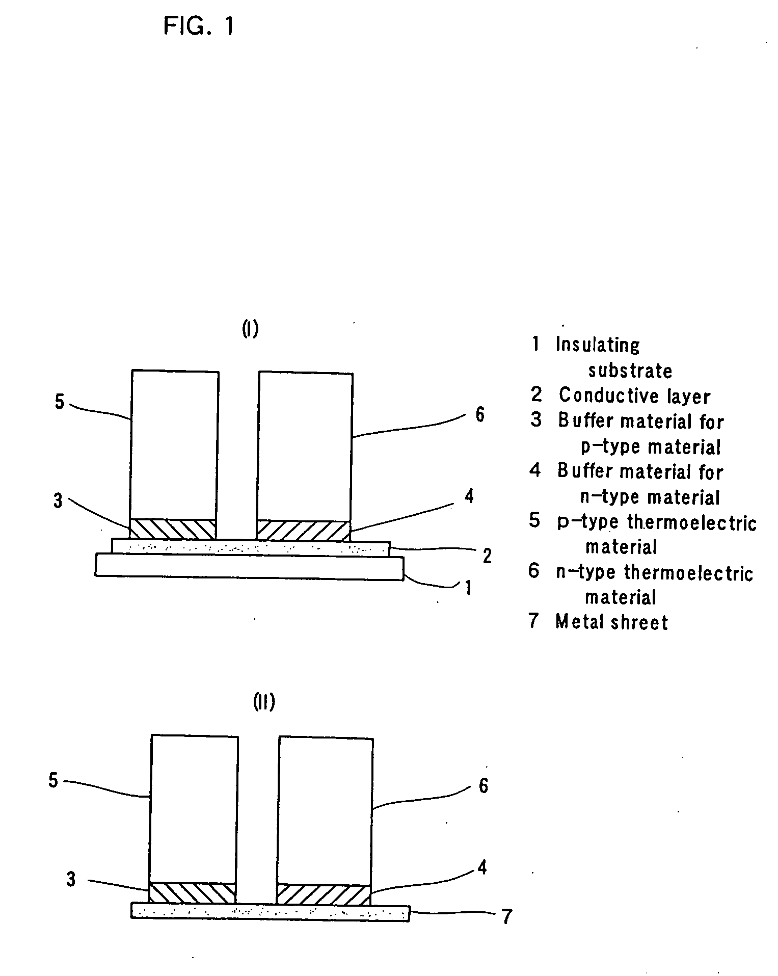
[0142] Thermoelectric elements were produced in the same manner as in Example 1 except for using materials as in Table 1 as thermoelectric materials, thermal buffer materials, and electrically conductive films to be formed on an alumina substrate. The thermoelectric elements obtained were shaped as shown in FIG. 1 (I).

TABLE 1CompositionCompositionMixingMixingElectricallyNet-likeof a p-typeof an n-typeComposition of a thermalRatioComposition of a thermalRatioconductiveor fibrousEx.thermoelectric materialthermoelectric materialbuffer for p-type materialA:Bbuffer for n-type materialA:Bfilmmaterial1Ca2.7Bi0.3Co4O9.3La0.9Bi0.1NiO3.0A: Ca2.7Bi0.3Co4O9.35:5A: La0.9Bi0.1NiO3.05:5AgNoneB: AgB: Ag2Ca2.7Bi0.3Co4O9.3LaNi0.9Cu0.1O2.9A: Ca2.7Bi0.3Co4O9.35:5A: LaNi0.9Cu0.1O2.95:5AgNoneB: AgB: Ag3Ca3Co4O9La2Ni0.9Cu0.1O3.9A: Ca3Co4O95:5A: La2Ni0.9Cu0.1O3.95:5AuNoneB: AuB: Au4Bi2Sr2Co2O9.3La0.9Bi0.1NiO3.0A: Bi2Sr2Co2O9.36:4A: La0.9Bi0.1NiO3.05:5AgNoneB: AgB: Ag5Bi1.8Pb0.2Sr2Co2O9.1LaNi0.9Cu0.1O2.8A...

example 6

[0143] A thermoelectric element was produced in the same manner as in Example 1 except for using a silver sheet with a length of 10 mm, a width of 5 mm, and a thickness of 100 μm as an electrically conductive substrate.

[0144] The thermoelectric element obtained was shaped as shown in FIG. 1 (II).


PUM


Abstract

The present invention provides a thermoelectric element comprising an electrically conductive substrate, a p-type thermoelectric material, and an n-type thermoelectric material; the p-type thermoelectric material being positioned on the substrate via an electrically conductive thermal buffer material, and the n-type thermoelectric material being positioned on the substrate via an electrically conductive thermal buffer material; wherein each thermoelectric material comprises a specific oxide and each electrically conductive thermal buffer material comprises an electrically conductive material having a thermal expansion coefficient between that of the thermoelectric material to which the thermal buffer material is bonded and that of the substrate. The invention also provides a thermoelectric module comprising a plurality of the thermoelectric elements. The thermoelectric element and the thermoelectric module have both a high thermoelectric conversion efficiency and excellent properties in terms of thermal stability, chemical durability, etc.

Description

TECHNICAL FIELD [0001] The present invention relates to a thermoelectric element, a thermoelectric module, and a thermoelectric conversion method. BACKGROUND OF THE INVENTION [0002] In Japan, only 30% of the primary energy supply is used as effective energy, with about 70% being eventually lost to the atmosphere as heat. The heat generated by combustion in industrial plants, garbage-incineration facilities and the like is lost to the atmosphere without conversion into other energy. In this way, we are wastefully discarding a vast amount of thermal energy, while acquiring only a small amount of energy by combustion of fossil fuels or other means. [0003] To increase the proportion of energy to be utilized, the thermal energy currently lost to the atmosphere should be effectively used. For this purpose, thermoelectric conversion, which directly converts thermal energy to electrical energy, is an effective means. Thermoelectric conversion, which utilizes the Seebeck effect, is an energy...

Claims


Application Information

Patent Timeline
IPC IPC(8): H01L35/28H01L35/12H01L35/14H01L35/20H01L35/08H01L35/22
CPCH01L35/08H01L35/22H10N10/817H10N10/855
Inventor FUNAHASHI, RYOJIMIKAMI, MASASHIMIHARA, TOSHIYUKIURATA, SAORIANDO, NAOKO
Owner NAT INST OF ADVANCED IND SCI & TECH
Why Eureka
Try Eureka