Thermopile infrared gas detector taking composite film as infrared absorption layer, and processing method of detector

An infrared absorption layer and gas detector technology, which is applied in the manufacture/processing of electrical radiation detectors, thermoelectric devices, and thermoelectric devices that only use the Peltier or Seebeck effect. problem, to achieve the effect of improving heat flux absorption, good flatness, and increasing duty cycle

Active Publication Date: 2014-04-02
ZHONGBEI UNIV
View PDF6 Cites 13 Cited by
  • Summary
  • Abstract
  • Description
  • Claims
  • Application Information

AI Technical Summary

Problems solved by technology

[0004] In order to solve the problems of low thermoelectric conversion rate of traditional thermopile infrared detectors and easy damage of suspension structure in the release process, the present invention provides a thermopile infrared gas detector with a composite film as an infrared absorption layer and a processing method thereof

Method used


Image

  • Thermopile infrared gas detector taking composite film as infrared absorption layer, and processing method of detector
  • Thermopile infrared gas detector taking composite film as infrared absorption layer, and processing method of detector
  • Thermopile infrared gas detector taking composite film as infrared absorption layer, and processing method of detector

Examples


Embodiment 1

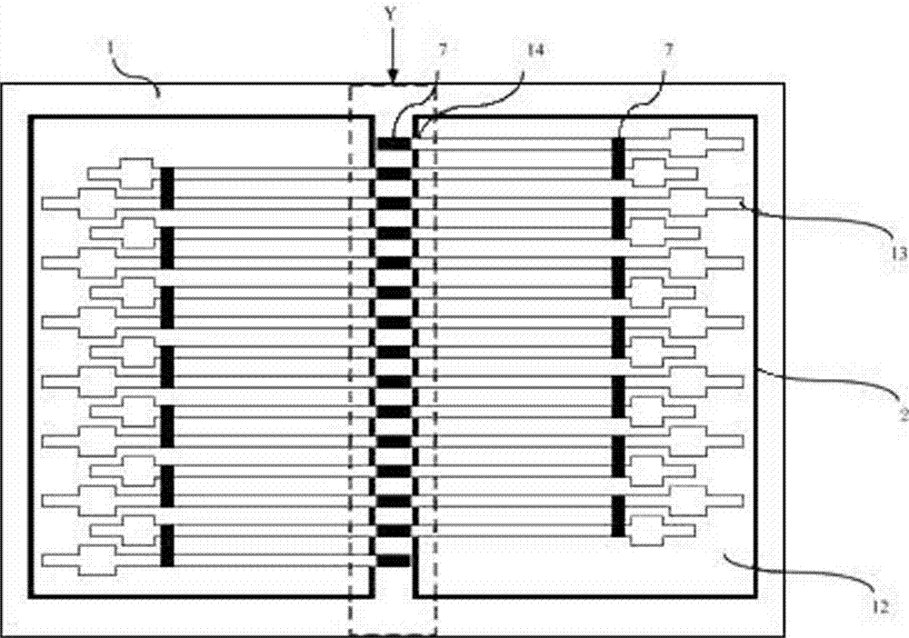
[0053] Embodiment 1: The main process steps include: selecting an SOI substrate as a device base, photoetching a square release hole, forming a closed isolation groove with the substrate, and controlling the range of dry release.

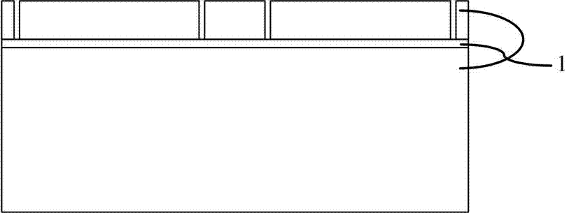
[0054] 1. LPCVD grows 5000? SiO2 as a dielectric support film, and LPCVD TEOS fills the isolation groove.

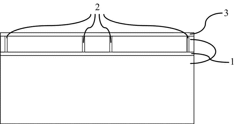
[0055] 2. LPCVD deposited 3000? POLY, ion implanted boron, dose 1.5E16cm-2, energy 50KeV.

[0056] 3. LPCVD deposited 1000? SiO2, LPCVD3000? POLY, ion implanted phosphorus, dose 1.5E16cm-2, energy 50KeV.

[0057] 4. Form the shape of P / N thermocouple strip by photolithography. The width of the thermocouple bar formed by photolithography in the Z-shaped structure is 3um, which can increase the effective heat conduction length and improve the thermoelectric conversion efficiency.

[0058] 5. Etch the top isolation layer of SiO2 by photolithography for 2000 ?, exposing the absorption region, pad and metal connection part.

[0059] 6. Preparati...

Embodiment 2

[0064] Example 2: The specific process steps are similar to Example 1, the main difference is that the junction between the cold end and the hot end of the N / P type thermocouple strip is not etched, and the connection between the cold end and the hot end of the thermocouple strip is made by metal connection. short circuit.

Embodiment 3

[0065] Example 3: The specific process steps are similar to Example 1, the main difference is that before releasing the polyimide, the window is etched on the absorbing layer film, which helps to reduce the release time, improve the release efficiency, and is more conducive to ensuring the suspension of the absorbing layer Film structure and maintaining film flatness.


PUM


Abstract

The invention belongs to the technical field of thermopile infrared gas detectors, and particularly relates to a thermopile infrared gas detector taking a composite film as an infrared absorption layer, and a processing method of the detector. The detector and the processing method solve the problems that the traditional thermopile infrared detector is low in thermoelectricity conversion rate and a suspension structure is damaged easily during a release course. The detector comprises an SOI (silicon on insulator) substrate, thermocouple strips, an SiO2 dielectric layer, metal connection and welding discs, SiO2 isolation layers and an absorption layer, wherein cold ends of the N/P polycrystalline silicon thermocouple strips are supported with the SOI substrate, and the absorption layer is arranged at the top of the detector in a suspension manner. According to the detector and the processing method, a higher absorption rate of the composite nano film to a near-infrared band is utilized, and the absorption layer is suspended above the detector, so that a unit duty ratio of the detector is increased, response and detection rates of the detector are increased correspondingly, and a performance index of the detector is optimized.

Description

technical field [0001] The invention belongs to the technical field of thermopile infrared gas detectors, and in particular relates to a thermopile infrared gas detector with a composite thin film as an infrared absorbing layer and a processing method thereof. Background technique [0002] Since W.herschel discovered infrared radiation in 1800, infrared detection technology has been widely used in military fields such as night vision devices, infrared guidance, and thermal imaging cameras, as well as civilian fields such as gas detection, public safety, and infrared temperature measurement. The working principle of the thermopile infrared detector is based on the Seebeck effect, that is, two different materials A and B have a common connection end as a hot end, and the other end is not connected as a cold end. When the hot end is heated, the A and B components An electrical potential is generated in the circuit to convert heat energy into electricity. The potential differen...

Claims


Application Information

Patent Timeline
Patent Type & Authority Applications(China)
IPC IPC(8): G01J5/12G01N21/3504H01L35/32H01L35/34
Inventor 谭秋林陈媛婧熊继军薛晨阳张文栋刘俊毛海央明安杰欧文陈大鹏
Owner ZHONGBEI UNIV
Why Eureka
Try Eureka