
Flat-plate-type thermoelectric generator and thermoelectric power generating component partition arrangement method

A technology of thermoelectric generator and thermoelectric power generation, which is applied in the direction of generator/motor, electrical components, engine components, etc.

Active Publication Date: 2018-07-31
JIANGSU UNIV
View PDF3 Cites 9 Cited by
  • Summary
  • Abstract
  • Description
  • Claims
  • Application Information

AI Technical Summary

Problems solved by technology

[0003] In order to solve the deficiencies of the existing thermoelectric generators used for waste heat recovery from automobile exhaust, the present invention proposes a flat-plate thermoelectric generator with good reliability and easy large-scale realization, which is installed between the three-way catalytic converter and the muffler of the automobile, and at the same time A partitioned layout method of thermoelectric power generation components based on the surface temperature distribution of the hot end is proposed, which improves the thermoelectric conversion efficiency of the thermoelectric generator, reduces the production cost of the thermoelectric generator, and facilitates the promotion of the thermoelectric generator

Method used


Image

  • Flat-plate-type thermoelectric generator and thermoelectric power generating component partition arrangement method
  • Flat-plate-type thermoelectric generator and thermoelectric power generating component partition arrangement method
  • Flat-plate-type thermoelectric generator and thermoelectric power generating component partition arrangement method

Examples


Embodiment Construction

[0079] The present invention will be further described below in conjunction with the accompanying drawings and embodiments, but the protection scope of the present invention is not limited thereto.

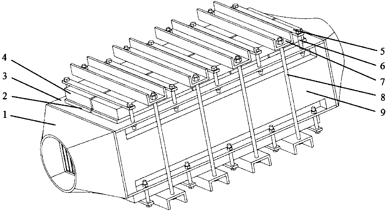
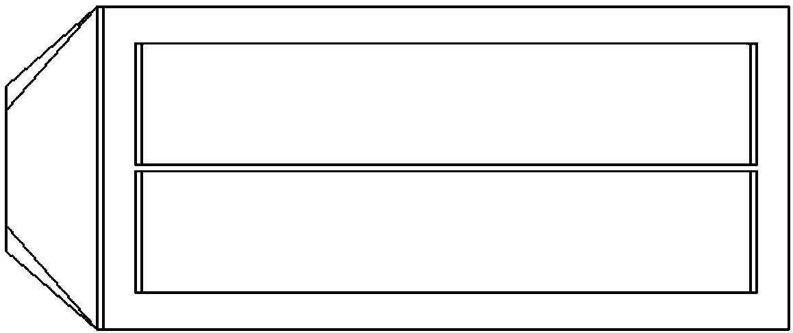
[0080] like figure 1 As shown, the flat-plate thermoelectric generator provided in this embodiment includes a heat collecting end panel 3, a heat insulating plate 9 and an end cover 1, and the heat collecting end panel 3, the heat insulating plate 9 and the end cover 1 Constitute a closed heat collection box, the number of the heat collection end panel 3, the heat insulation plate 9 and the end cover 1 is two, and the two heat collection end panels constitute the upper and lower two of the heat collection box. On the end face, two heat shields form the left and right sides of the heat collection box, and the two end covers 1 form the inlet and outlet of the heat collection box respectively. Heat collecting fins are distributed on one end surface of the heat collecting end panel 3...


PUM


Abstract

The invention relates to a flat-plate-type thermoelectric generator and a thermoelectric power generating component partition arrangement method. The flat-plate-type thermoelectric generator comprisesan end cover, a heat collecting end panel to which the heat collecting fins are attached, a heat insulation board, a thermoelectric power generation component, a water cooling head and a guide cold block compaction mechanism. The thermoelectric power generating component partition arrangement method of the flat-plate-type thermoelectric generator mainly comprises the following steps of accordingto the structure parameter of the flat-plate-type thermoelectric generator, calculating a total heat exchange amount; according to a specific size, carrying out partitioning; calculating the convection heat exchange amount of each area and acquiring the temperature distribution of an internal wall surface; and calculating and acquiring the temperature distribution of an external surface, and partitioning and arranging the thermoelectric power generating components of different work sections. In the invention, vehicle exhaust and waste heat are recycled to carry out power generation; accordingto a specific usage condition, the thermoelectric power generating components are arranged in a partitioning mode; and thermoelectric conversion efficiency is increased and cost is effectively reduced.

Description

technical field [0001] The invention belongs to the field of thermoelectric power generation, and relates to a novel flat-plate thermoelectric generator and a partition arrangement method of its thermoelectric power generation components. Background technique [0002] The thermoelectric generator is a device that directly converts heat energy into electrical energy by using the Seebeck effect of semiconductor materials. The device has the advantages of compact structure, green environmental protection, no noise during operation, and long service life. At present, the number of automobiles is increasing, and the waste heat emitted by automobiles is also increasing, which is a waste of resources. The thermoelectric generator can reduce the waste of such resources, and at the same time, the generated electric energy can be supplied to the consumption of automotive electronic parts, increasing fuel economy. However, the existing thermoelectric generator has a complex structure,...

Claims


Application Information

Patent Timeline
IPC IPC(8): H02N11/00F01N5/02
CPCF01N5/025H02N11/002Y02T10/12
Inventor 汪若尘周润泽余未孟祥鹏陈龙
Owner JIANGSU UNIV
Learn More