
Disk drive with reduced thermal expansion induced disk slip

a technology of thermal expansion and disk slip, which is applied in the direction of magnetic circuit rotating parts, magnetic circuit shape/form/construction, instruments, etc., can solve the problems of creating certain design problems, the above-described spindle motor design may have certain problems, and the result is commonly referred to as "disk slip"

Inactive Publication Date: 2001-02-06
WESTERN DIGITAL TECH INC
View PDF16 Cites 61 Cited by
  • Summary
  • Abstract
  • Description
  • Claims
  • Application Information

AI Technical Summary

Problems solved by technology

While this advancement has provided highly beneficial results, inherent characteristics of the spindle motor components and the disk media have also created certain design problems, as described below.
The above-described spindle motor design may have certain problems due to the particular materials used for various components.
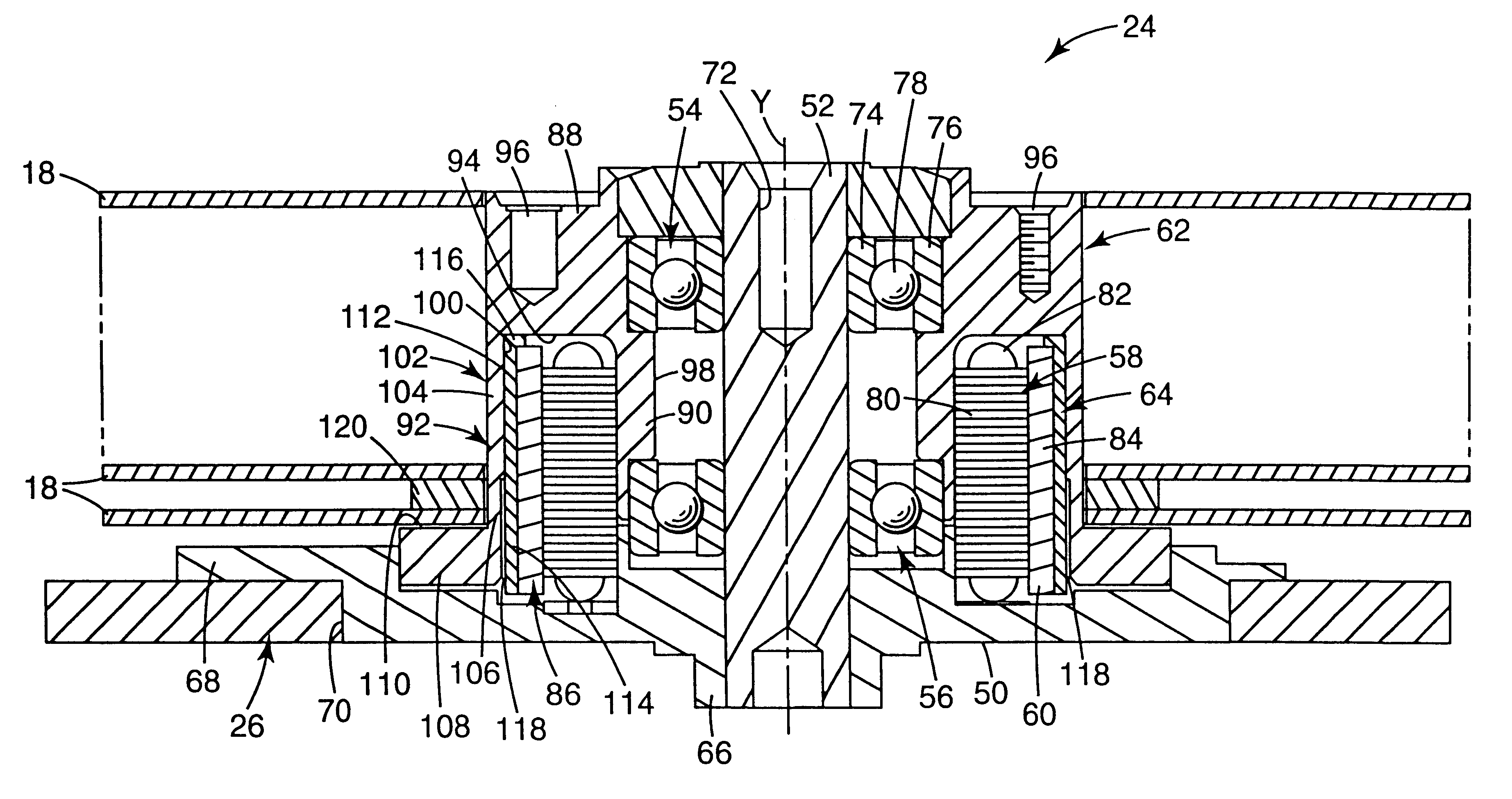
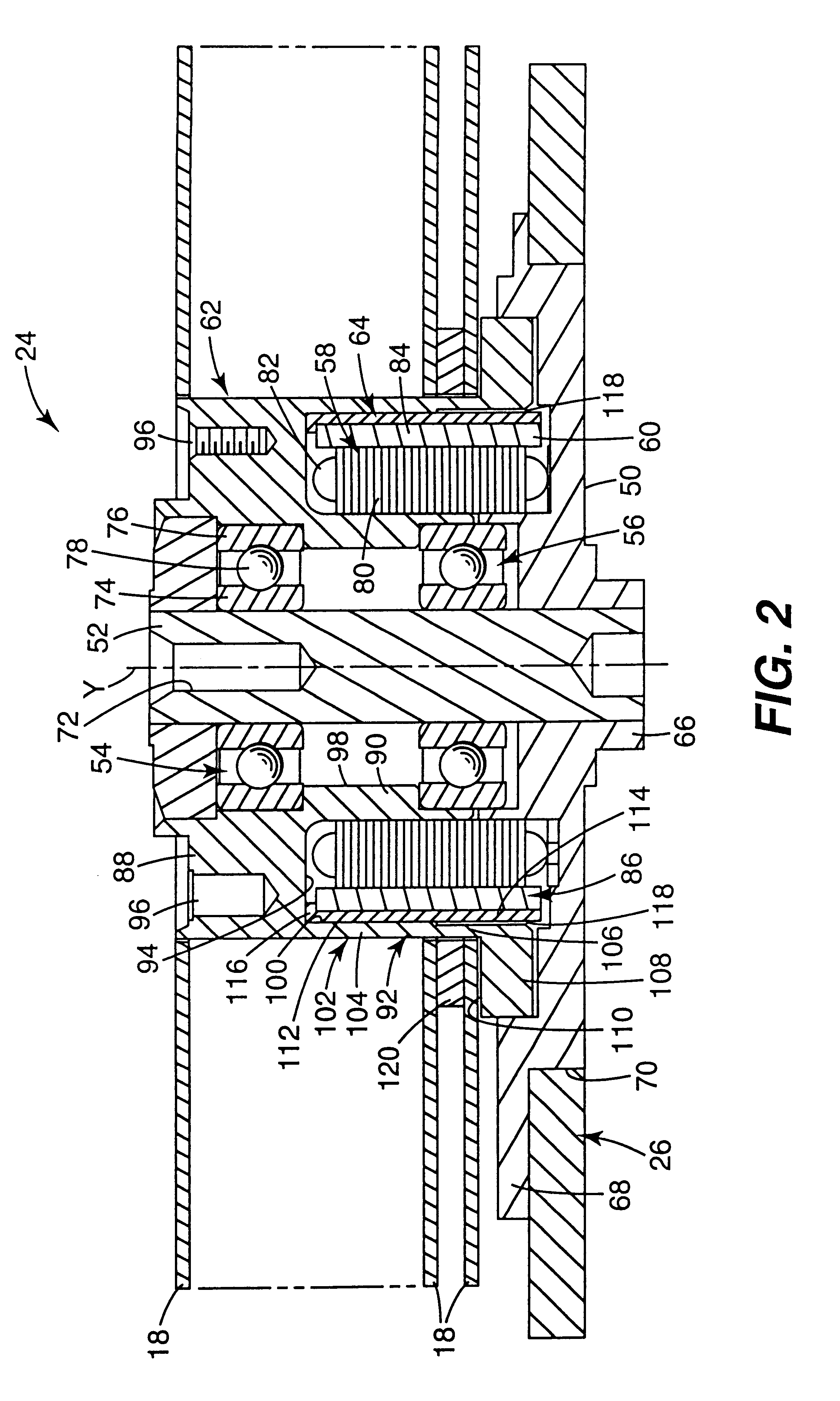
Because the disk drive, including the spindle motor and disks, is normally subjected to a wide temperature variation during manufacture subsequent storage and operation in a host computer, the resulting difference in thermal expansion may result in what is commonly referred to as "disk slip."
The back iron impedes this natural contraction.
However, an aluminum disk abutting the hub flange will contract and once the friction between the contact surface of the hub flange and the disk is overcome by the disk, disk slip may occur.
However, a spindle motor using such an approach is difficult to assemble which increases the costs of manufacturing the spindle motor.

Method used


Image

  • Disk drive with reduced thermal expansion induced disk slip
  • Disk drive with reduced thermal expansion induced disk slip
  • Disk drive with reduced thermal expansion induced disk slip

Examples


Embodiment Construction

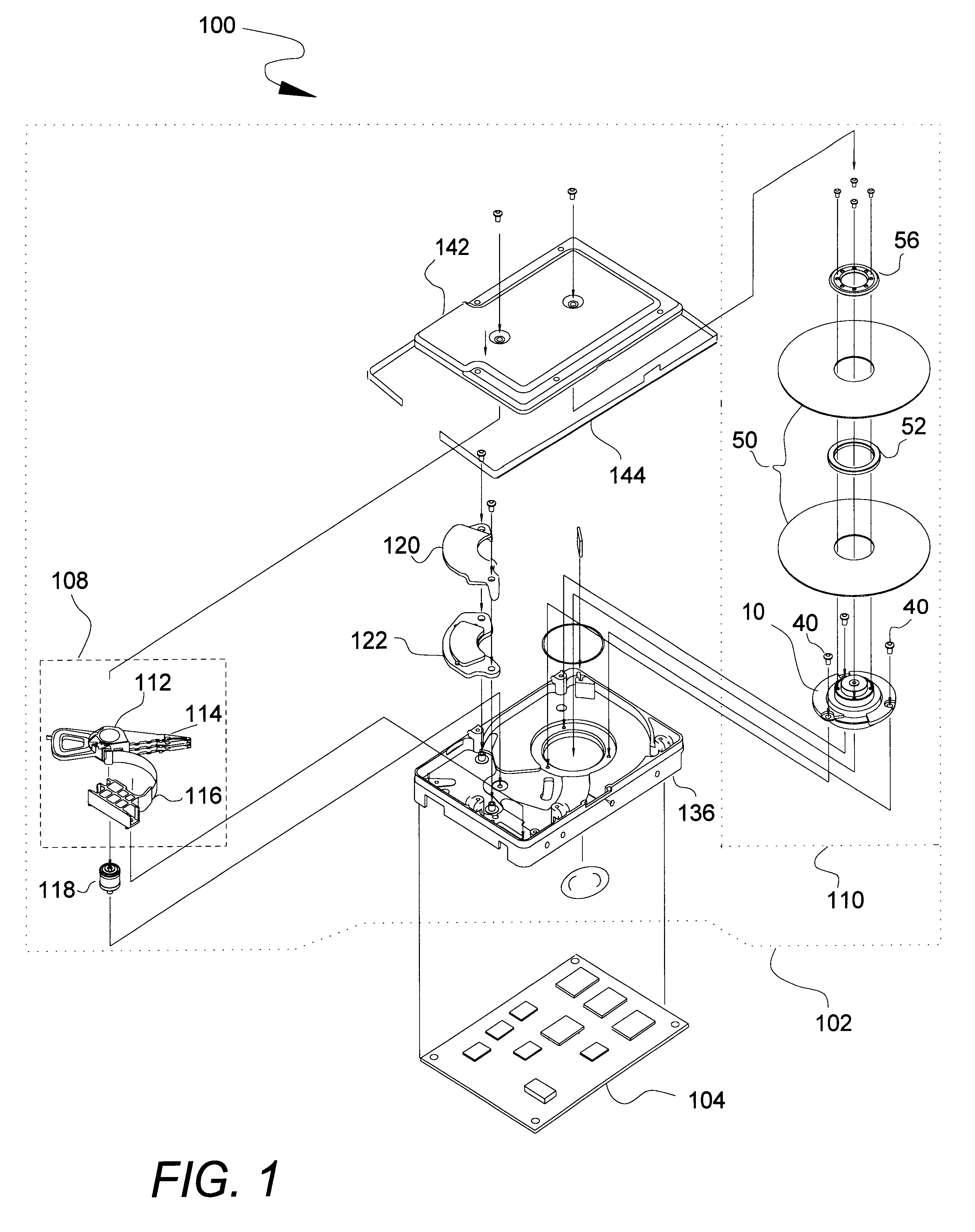
As shown in FIG. 1, a disk drive 10 embodying one preferred embodiment of the present invention includes a head disk assembly 12 and a printed circuit board assembly 14. The printed circuit board assembly 14 is suitably secured to an exterior of the head disk assembly 12 and controls operation of various components thereof

The head disk assembly 12 includes an enclosure 16, a magnetic disk 18, a magnetic transducer 20, a rotary actuator arrangement 22 and a spindle motor generally indicated at 24. As described in greater detail below, the magnetic disk 18, the magnetic transducer 20, the rotary actuator arrangement 22 and the spindle motor 24 are maintained within the enclosure 16.

The enclosure 16 comprises a base 26 and a cover 28. The enclosure 16 is sealed to provide a relatively contaminant-free interior for remaining components of the head disk assembly 12. Suitably, a tape seal 30 is used to seal the enclosure 16.

The magnetic disk 18 and the magnetic transducer 20 are positione...


PUM


Abstract

A spindle motor for a disk drive includes a shaft, an aluminum hub, a bearing, a magnetic steel back iron, and a magnet. The hub includes an axial wall having an inner surface. The back iron has an upper portion and a lower portion. The hub is concentrically position about the shaft such that the inner surface extends along a direction of a longitudinal axis defined by the hub. The bearing is positioned between the hub and the shaft. The back iron is secured to the hub such that the upper portion abuts the inner surface, whereas the lower portion is spaced-apart radially from the inner surface, thereby forming a single gap between the back iron and the hub. Finally, the magnet is attached to the back iron such that an axial length of the magnet is substantially coextensive with an axial length of the back iron.

Description

1. Field of the InventionThe present invention relates to hard disk drives. More particularly, it relates to a disk drive spindle motor configured to reduce thermal expansion induced disk slip.2. Description of the Prior Art and Related InformationA huge market exists for mass-market host computer systems such as servers, desktop computers, and laptop computers. To be competitive in this market, a hard disk drive must be relatively inexpensive, and must accordingly embody a design that is adapted for low-cost mass production. Numerous manufacturers compete in this huge market and collectively conduct substantial research and development, at great annual cost, to design and develop innovative hard disk drives to meet increasingly demanding customer requirements.Each of numerous contemporary mass-market hard disk drive models provides relatively large capacity, often in excess of 1 gigabyte per drive. Nevertheless, there exists substantial competitive pressure to develop mass-market h...

Claims


Application Information

Patent Timeline
IPC IPC(8): G11B33/14G11B19/20G11B25/04G11B33/12H02K1/28H02K7/14
CPCG11B19/2009G11B25/043G11B33/121G11B33/1433H02K1/28H02K7/14
Inventor CHAMBERLAIN, STANLEY CASE
Owner WESTERN DIGITAL TECH INC
Learn More