
Switch device

a technology of a switch and a switch body, which is applied in the direction of contact fixed to the operating part, contact fixed to the substrate, electrical equipment, etc., can solve the problems of contact failure, short circuit, dust or water droplet contamination,

Active Publication Date: 2019-10-10
KK TOKAI RIKA DENKI SEISAKUSHO +1
View PDF3 Cites 4 Cited by
  • Summary
  • Abstract
  • Description
  • Claims
  • Application Information

AI Technical Summary

Benefits of technology

The invention provides a switch device that can prevent foreign objects like dust and waterdrops from entering it.

Problems solved by technology

However, in this type of switch in the related art, since an air vent hole communicating with the space formed between the movable contact plate and the switch substrate is provided in the shield plate covering the movable contact plate, ingress of foreign matter such as dust or a water droplet may occur.
In a case where foreign matter ingresses into and accumulates in this space, there is a possibility that a contact failure, a short circuit, or the like may occur between the movable contact plate and the stationary switch contact of the switch substrate, which is not preferable.

Method used


Image

  • Switch device
  • Switch device

Examples


Embodiment Construction

[0018]A switch device according to embodiments will be described below with reference to the accompanying drawings.

[0019]Overall Configuration of a Switch Device Embodiments to be described below can be applied to switch devices of various devices such as vehicle-mounted device such as air conditioners and door mirrors, remote operation devices such as personal computers and mobile phones, home electrical devices such as refrigerators and washing machines.

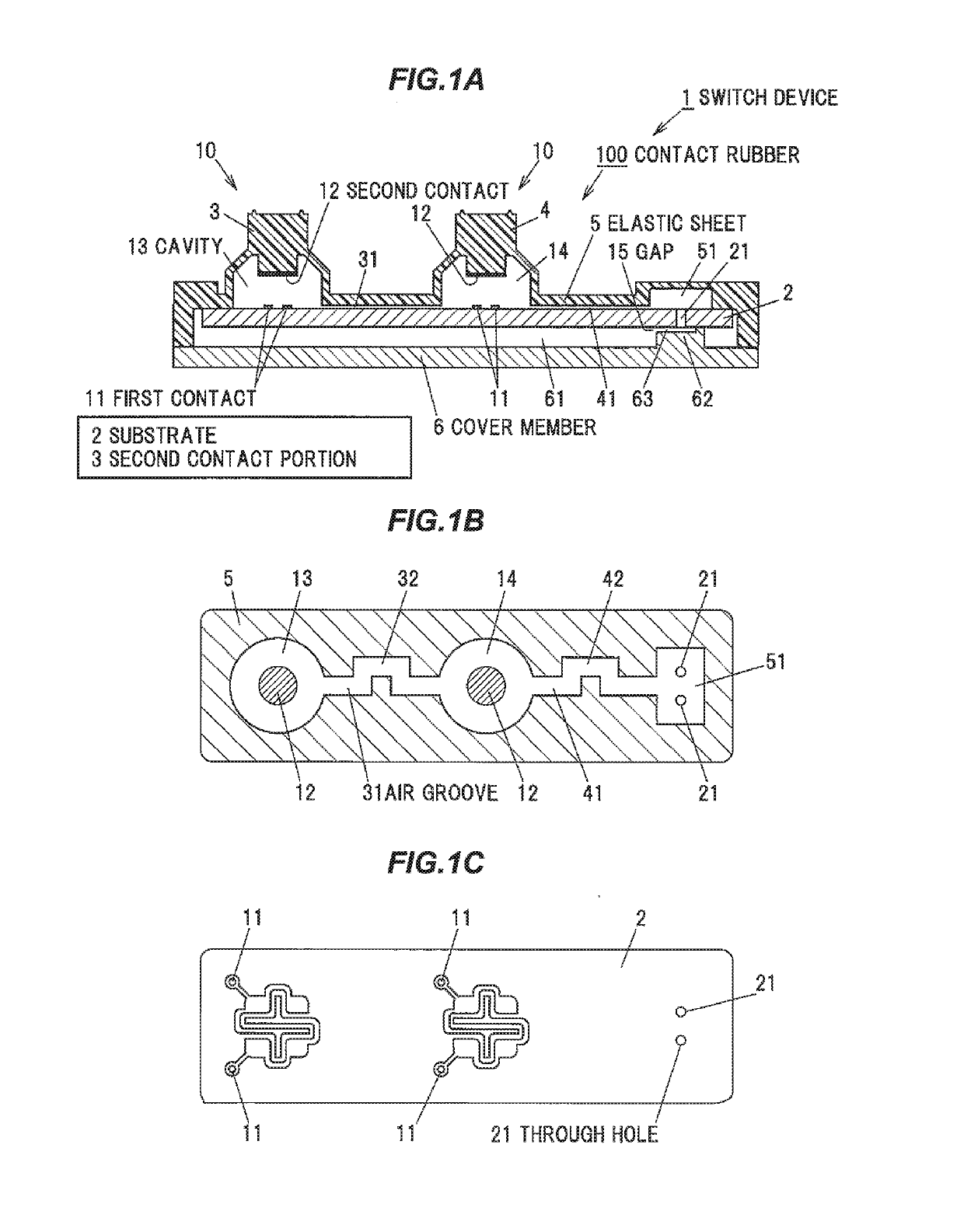
[0020]In FIG. 1A, the switch device 1 includes two switch portions, which are a first switch portion 10 and a second switch portion 10, configured to perform a switch operation in response to a pressing operation of an operation member. Each of the switch portions 10 is constituted by, two first contacts 11 and 11 electrically connected to the wiring of the substrate 2, and an elastically deformable and dome-shaped first or second second contact portion 3 and 4 including a second contact 12 capable of contacting to and separating f...


PUM


Abstract

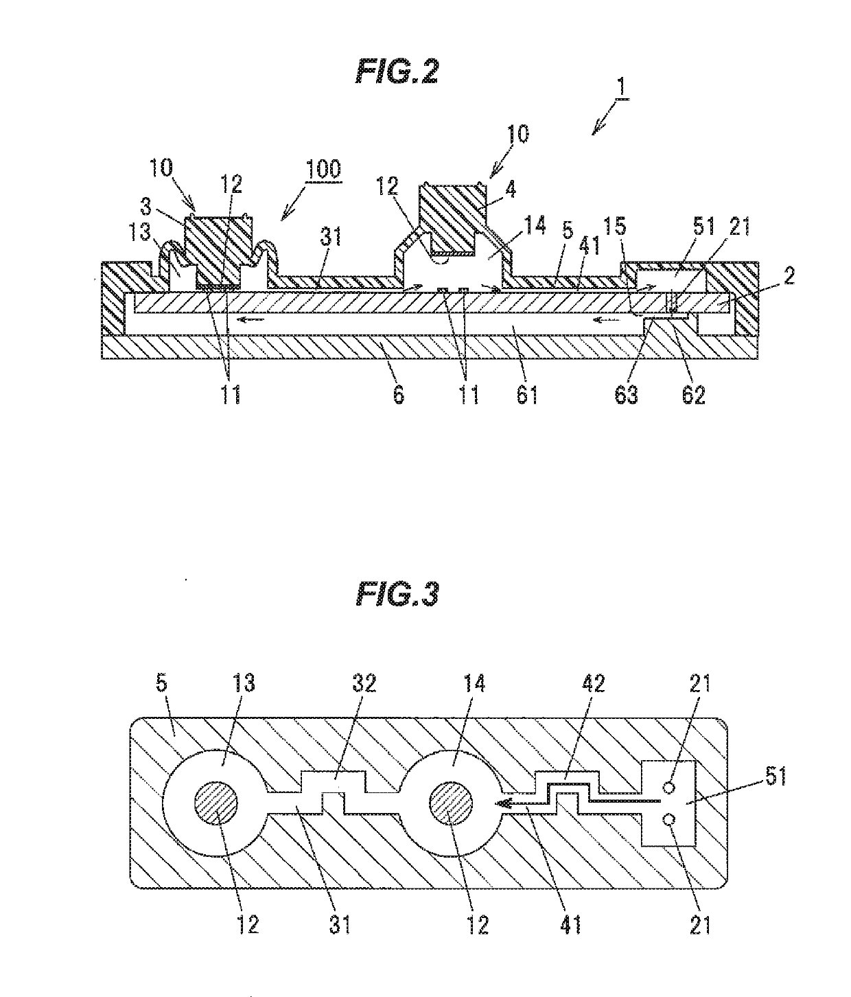
A switch device includes a substrate provided with at least one first contact and including at least one through hole, and a contact rubber, being an elastic sheet covering the substrate, provided with a dome-shaped cavity configured to make a second contact portion including a second contact corresponding to the first contact elastically deformable to be capable of contacting to and separating from the first contact, a vent cavity portion provided corresponding to the through hole, and an air groove communicating with the cavity and the vent cavity portion between the substrate and the elastic sheet. The air groove includes a non-linear path.

Description

BACKGROUNDTechnical Field[0001]The present invention relates to a switch device, and more particularly to a switch device having a structure for suppressing ingress of foreign matter.Related Art[0002]As an example of a switch device in the related art, there is a switch having a structure in which an inversion plate (a movable contact plate) formed by forming an elastic metal plate in a dome shape is mounted on a stationary switch contact of a switch substrate (for example, JP 2005-158720 A).[0003]In the switch in the related art disclosed in JP 2005-158720 A, a flexible shield plate covering the movable contact plate is provided over the switch board. The shield plate is piercingly provided with an air vent hole that communicates with a space formed between the movable contact plate and the switch substrate and also communicates with the outside air.[0004]Pressing the shield plate turns the switch to ON-state by the movable contact plate being inverted, causing the movable contact ...

Claims


Application Information

Patent Timeline
Patent Type & Authority Applications(United States)
IPC IPC(8): H01H13/06H01H13/14
CPCH01H13/06H01H2205/004H01H2205/002H01H13/14H01H13/82H01H2213/002H01H2213/006H01H2213/014H01H13/10
Inventor OGAWA, SHOFUNAYAMA, TOMOYUKIOHTA, YASUHISAGOTO, YUYATAKADA, NAOYUKI
Owner KK TOKAI RIKA DENKI SEISAKUSHO
Learn More