Self-locking descender with disengageable handle

Active Publication Date: 2019-10-17
ZEDEL CORP
View PDF0 Cites 3 Cited by
  • Summary
  • Abstract
  • Description
  • Claims
  • Application Information

AI Technical Summary

Benefits of technology

[0018]It is particularly advantageous to provide for the first pin to be formed by a rod movable in rotation, the second ramp forcing the rod to swivel to interrupt the first mechanical link an

Problems solved by technology

It has become apparent from use that a large number of users have difficulty in keeping the handle just below the threshold position corresponding to interruption of the mechanical connection between the handle and cam.
When descending along a slope with a gentle incline, use

Method used


Image

  • Self-locking descender with disengageable handle
  • Self-locking descender with disengageable handle
  • Self-locking descender with disengageable handle

Examples


Embodiment Construction

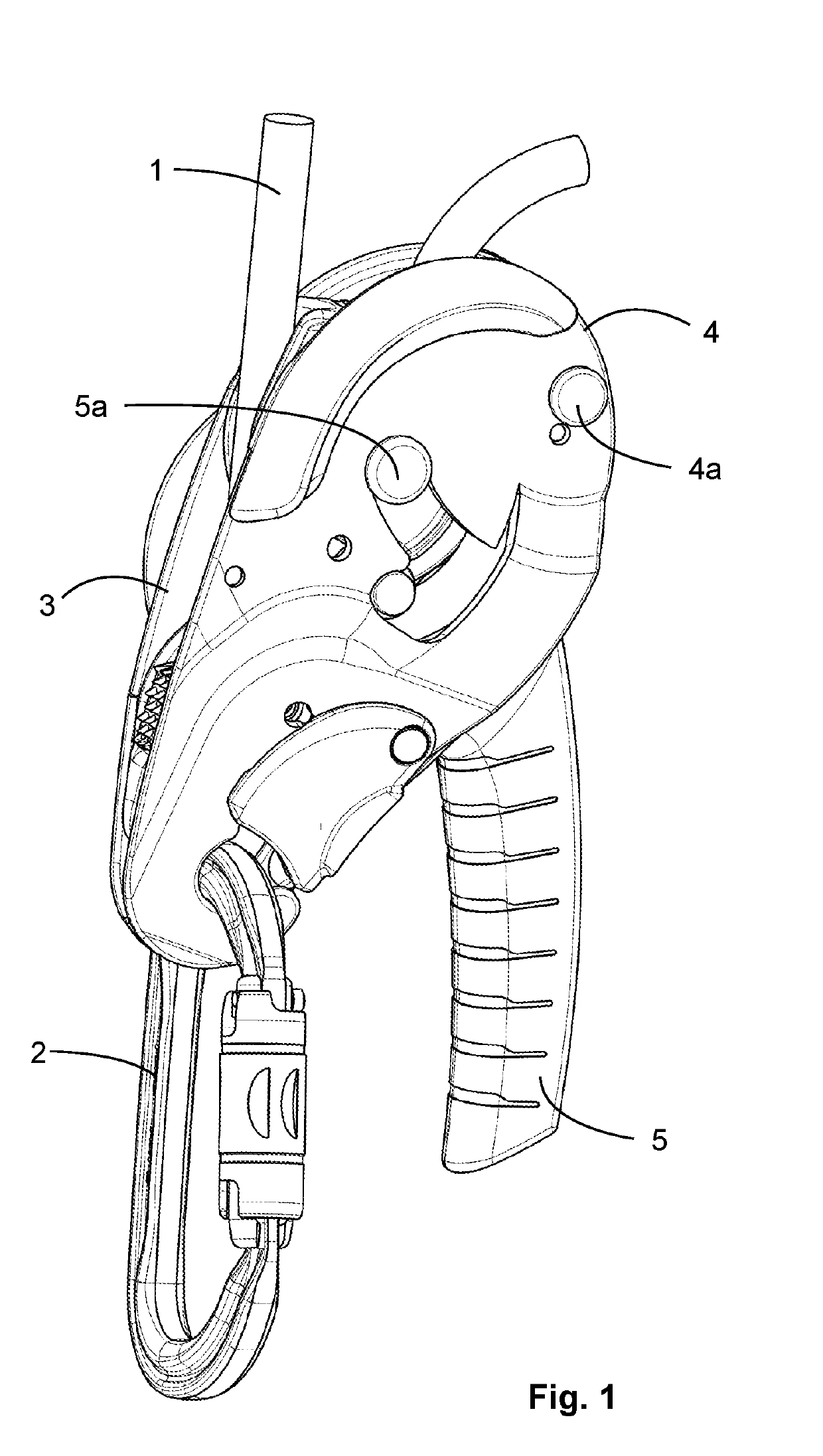
[0037]FIG. 1 illustrates a self-locking safety descender for descending on a rope 1. The descender is provided with a through-hole designed to operate in conjunction with a connector 2, for example a carabiner, in order to attach the descender to the user and advantageously to attach the descender to a harness worn by the user.

[0038]The descender has two inlet / outlet openings that communicate with one another for rope 1 to run inside the descender. In the illustrated embodiment, the descender is provided with a first flange 3 presented as a fixed flange and a second flange 4 presented as a movable flange. In the illustrated example, movable flange 4 is mounted movable in rotation with respect to fixed flange 3 around a swivel-pin 4a. Other configurations can be envisaged. First and / or second flanges 3 and 4 can be made from metal, for example from aluminium or aluminium alloy or from steel or from another iron-based alloy. Second flange 4 is advantageously swivel-mounted to enable r...


PUM


Abstract

The descender comprises a handle and a cam that are movable between a securing position and a sliding position of the rope. The cam defines a first stop and a second pin. The handle has a first pin coming into contact with the first stop to form a first mechanical link and a second stop coming into contact with the second pin. Movement of the handle results in movement of the cam between the securing and sliding positions. In a threshold position of the handle, the first mechanical link is interrupted and the cam returns to the securing position. The second stop is movable with respect to the handle by means of a spring. When movement of the handle takes place, the second pin comes into contact with the second stop before the handle stresses a spring and reaches the threshold position.

Description

FIELD OF THE INVENTION[0001]The invention relates to a self-locking descender for descending along a rope.STATE OF THE ART[0002]The document EP 688,581 filed by the applicant describes a descender of the kind mentioned in which the manual actuating handle is connected to the pulley by a mechanical link with a toggle-joint. Descending movement of the user is enabled when the handle is moved to an intermediate position in which the cam is released. Double securing of the rope is possible in the loaded state for two distinct positions of the handle:[0003]either a raised position after the handle has been released,[0004]or after disengagement of the mechanical link when the handle is lowered beyond the intermediate position.After disengagement, the mechanism has to be reset to re-establish the mechanical link. The disengagement threshold depends on the angular position of the handle and on the force to be exerted depending on the load applied on the apparatus.[0005]The document EP 2,018...

Claims


Application Information

Patent Timeline
IPC IPC(8): A62B1/14
CPCA62B1/14
Inventor CHABOD, PIERRE-OLIVIERQUILLARD, CHRISTOPHEBERGEZ, AURÉLIE
Owner ZEDEL CORP
Why Eureka
Try Eureka