Bulging Torus Balloon

a balloon and torus technology, applied in the field of balloons, can solve the problems of affecting the flow of blood to other sites near the targeted site, requiring multiple operations, injury to said other sites or requiring multiple operations, etc., to avoid ischemic injury, relieve such heart strain, and remove or dissolve clots in a short time.

Active Publication Date: 2019-10-24
WALZMAN DANIEL EZRA
View PDF1 Cites 6 Cited by
  • Summary
  • Abstract
  • Description
  • Claims
  • Application Information

AI Technical Summary

Benefits of technology

[0009]The present invention offers several dramatic improvements over the prior art. These include first, by channeling the blood down the center of the vessel, the blood is prevented from shearing off debris from the vessel walls, thus preventing the difficulties associated with adding debris to a bloodstream. Second, by channeling the blood down the center of the vessel, less pressure is necessary to move the blood to where it is intended, thus reducing the difficulties associated with elevated blood pressure. Third, the shape of the device of the present invention minimizes recoil and displacement. Fourth, the current device allows continued blood flow through said balloon, and thus through the vessel it is deployed in, even when said balloon is fully inflated.
[0010]The present invention can also combine a temporary bulging torus shaped balloon and another unique support catheter or procedural catheter. For example, the balloon of the current invention can be deployed across the origin of an injured and bleeding branch artery, to ameliorate said bleeding, while allowing continued blood flow in the parent artery, through the central hole / lumen of said bulging torus / cylinder balloon. In another embodiment, a bulging torus balloon can be used in the aorta to pin a second catheter in position within the origin of one of the great vessels, to prevent recoil of said second catheter into the aorta while wires or other devices are advanced distally through said second catheter. In some procedures this can allow adequate distal wire access to subsequently allow further egress of said second catheter towards a target location, over said wire.
[0011]In order to prevent recoil and displacement, the present invention deploys a bulging torus shaped balloon which is inflated until said balloon fit snuggly against the inside of the vessel in which the present invention is deployed, thus allowing the support for fixing the catheter element of the present invention, or a second catheter or other device that is delivered separately alongside it. Said balloon is affixed to the catheter element of the present invention. The medical device disclosed by the present invention teaches a unique vessel-anchoring shape which combines static and dynamic features to ameliorate recoil and displacement. In particular, the cylindrical outer surface allows for maximum friction while blood flowing through the center of the device provides additional radial force to enhance anchoring. The present invention teaches both the use of a passage shaped by a cylindrical element as well as a passage shaped by a truncated cone.
[0012]More particularly, the current invention teaches an embodiment wherein said first passage has a blood-entry hole which is greater in size than the blood-exit hole at the other end of said passage. Such an alignment forms a truncated conical section which enhances the radial anchoring force resulting from blood flowing into a larger opening than it exits.
[0013]Said balloon element is located at any point along a delivery hypotube / catheter or other device capable of delivering the balloon of the current invention. The delivery device or catheter must include least one port that is capable of overlapping a corresponding port within the second passage of the present invention. Said ports facilitates the delivery and remove of fluid or air into and out of said balloon, in order to inflate and deflate said balloon as desired.
[0015]Additionally, in some embodiments, said balloon can be used to perform angioplasty and open a blockage. There is a critical advantage to this device in that it allows temporary flow of blood to avoid ischemic injury, with immediate restoration of a degree of flow beyond a vessel blockage. This will allow additional time to remove or dissolve a clot while allowing flow to the at-risk tissue. Additionally, in the case of pulmonary emboli which are large there is an additional issue of heart strain due to the lack of outflow from the right side of the heart, the balloon described here can be deployed within the pulmonary embolus and can also help relieve such heart strain by allowing outflow from the right heart past said clot when there are large pulmonary emboli in the main pulmonary arteries. Additionally, the balloon of the current invention can be used for balloon-assisted embolization.

Problems solved by technology

One of the problems associated with using balloons is that although control of the blood flow through a portion of the blood vessel is achieved, including blockage of the blood supply to a targeted site, blood flow is completely interrupted to other sites near the targeted site.
However, complex medical procedures may not be achieved during said short duration resulting in injury to said other sites or requiring multiple operations at the same targeted site.
Other problems associated with balloons include the number of positioning changes required each time a balloon is deflated to allow flow, to avoid ischemia.
The prior art also results in longer procedure time, increased radiation exposure for the patients and staff, as well as increased risk of morbidity.
Furthermore, in some vessels blood flow is so critical that temporary balloon occlusion for even relatively short periods of time is not tolerated.
This limits the ability to use balloons to pin catheters or other devices for support in such vessels, resulting often in unwanted recoil of said device, and the inability to efficiently, effectively and safely achieve the procedural goal.
Additionally, in many anatomical situation access to some vessels can be difficult.
If the catheter does not have adequate physical support to resist such kickback, it will fall out of the desired position.
In some cases this could prevent appropriate access to the desired pathological region altogether.
In other cases, it can create complications during a procedure when catheters and devices suddenly kickback and are dislodged from the desired location.
Such movement is undesirable.

Method used


Image

  • Bulging Torus Balloon
  • Bulging Torus Balloon
  • Bulging Torus Balloon

Examples


Embodiment Construction

[0020]The present invention is composed of a temporarily bulging torus shaped bypass balloon 10 comprising two passages. One passage further comprises a port.

[0021]The outer diameter of said balloon is 0.001 cm-30 cm. The inner diameter of said balloon element is 0.0001 cm-29 cm.

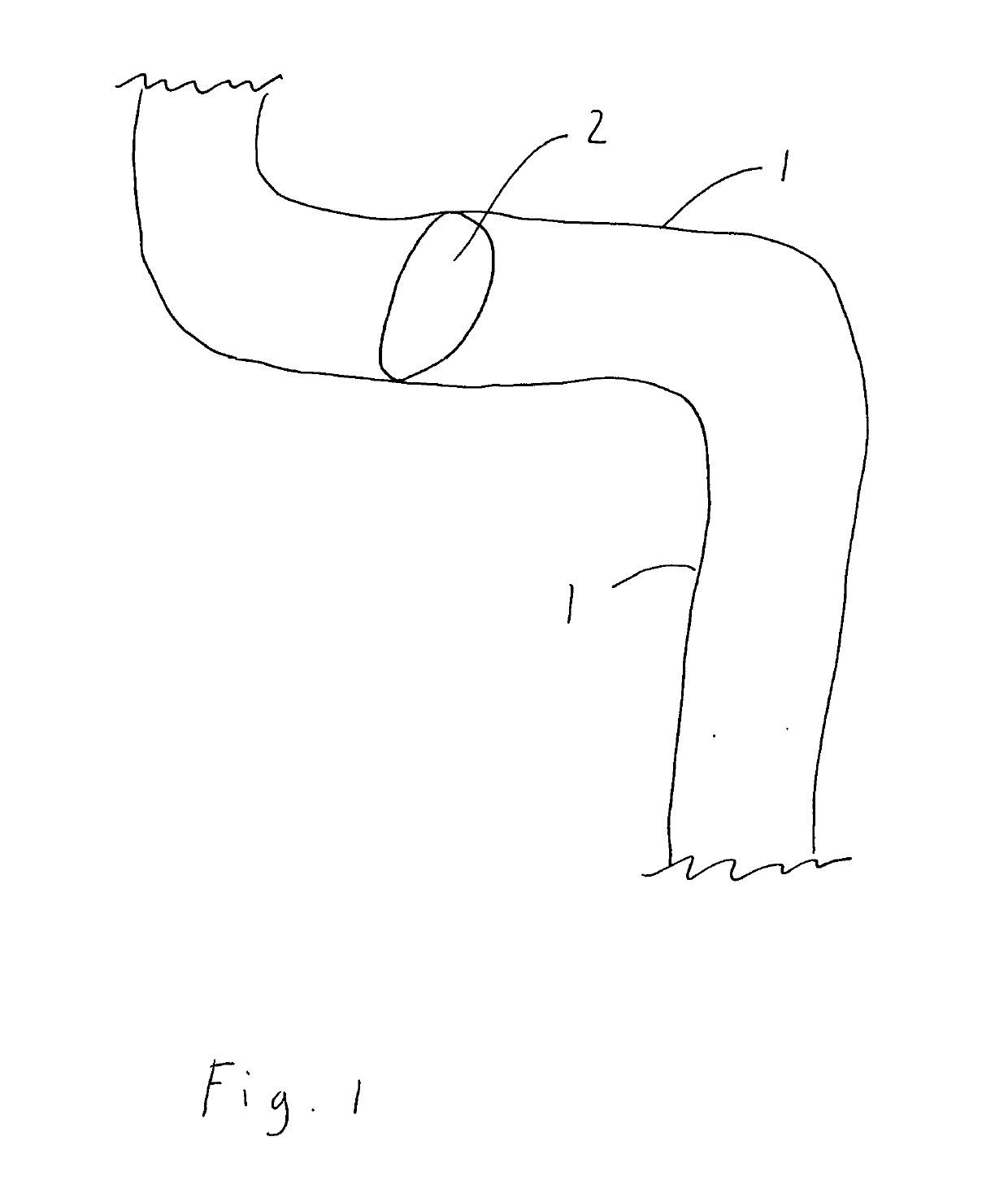
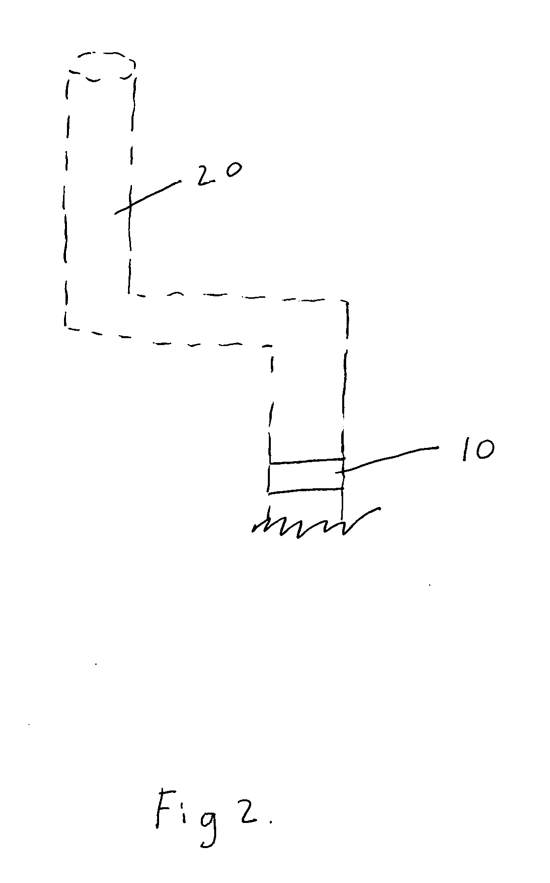
[0022]The present invention is capable of inflating and deflating prior to deployment within a vessel wall 1. Referring to FIG. 2, the bulging torus-shaped balloon 10 of the current invention is depicted in a deflated state disposed upon delivery catheter 20 (shown with dotted lines as not part of the invention).

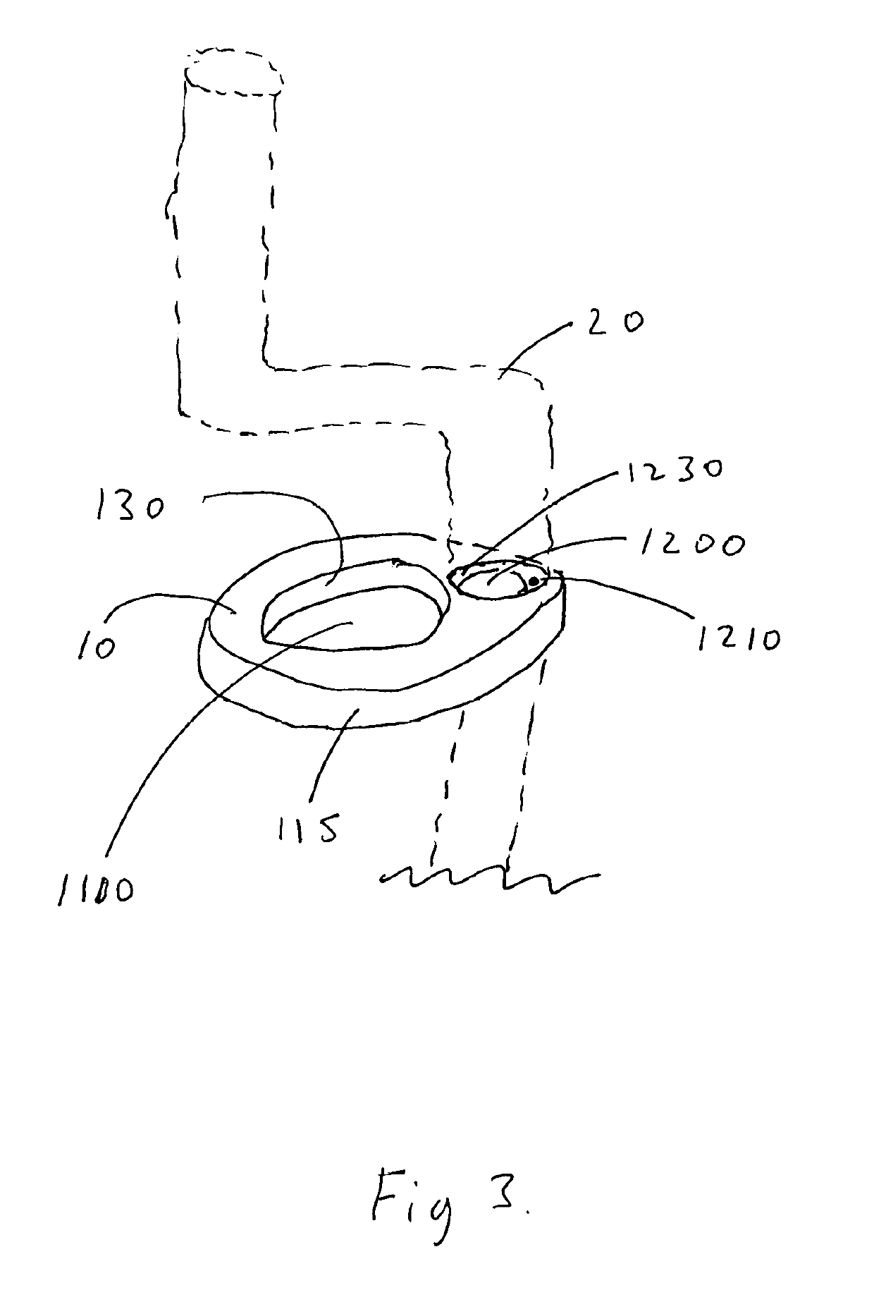
[0023]FIG. 3 depicts the bulging torus-shaped balloon 10 in a fully inflated, deployed state disposed upon delivery catheter 20 (shown with dotted lines). Second passage 1200 allows the delivery device 20 to pass therethrough. First passage 1100 allows for blood to flow through the center of the present invention. Port 1210 within second passage 1200, more particularly on second passage interior wall...


PUM


Abstract

The present invention is a medical device for anchoring itself and other medical devices while channeling blood flow through the center of a vessel proximal to the device's target area to minimize debris and the pressure necessary to move blood proximal to the device of the present invention. It also provides superior recoil reduction capabilities. Disclosed is a bulging torus or doughnut-shaped balloon medical device that may be inflated and deflated by increasing and decreasing pressure within the balloon, having two passages therethrough, dimensioned for blood flow and a delivery device. A method using the device is also disclosed.

Description

FIELD OF THE INVENTION[0001]The present invention relates generally to medical device used in medical procedure, specifically to a cylindrical balloon to ameliorate ischemic injury during balloon inflations.BACKGROUND OF THE INVENTIONDiscussion of the Prior Art[0002]The use of devices in conjunction with medical procedures for controlling blood flow in a blood vessel is taught by the prior art. Among the most common is a balloon catheter. The balloon catheter, such as taught in the prior art, may be used to achieve isolation of a body part from its blood supply. Balloons can also be used sometimes to help pin another device in a certain position temporarily.[0003]One of the problems associated with using balloons is that although control of the blood flow through a portion of the blood vessel is achieved, including blockage of the blood supply to a targeted site, blood flow is completely interrupted to other sites near the targeted site. This shortcoming can be tolerated for a short...

Claims


Application Information

Patent Timeline
Patent Type & Authority Applications(United States)
IPC IPC(8): A61M25/10
CPCA61M25/104A61M25/1002A61M2025/1095A61M2025/1061A61M2025/1097
Inventor WALZMAN, DANIEL EZRA
Owner WALZMAN DANIEL EZRA
Why Eureka
Try Eureka