Adaptive upscaling of cloud rendered graphics

a cloud rendering and video upscaling technology, applied in the field of video upscaling and rendering process, can solve the problems of affecting the response and execution speed of the application, affecting the performance of the application, so as to achieve the effect of increasing the density of the virtual machin

Active Publication Date: 2019-11-07
NVIDIA CORP
View PDF11 Cites 9 Cited by
  • Summary
  • Abstract
  • Description
  • Claims
  • Application Information

AI Technical Summary

Benefits of technology

The patent text describes a method and system for improving the performance of video rendering on a server system. The system uses a combination of compression algorithms and a video rendering engine to determine the optimal way to allocate system resources and deliver video to clients. The video rendering system can dynamically shift video rendering to the client device based on its video rendering capability, and uses a filter map to indicate connection relationships between color pixels. The system also utilizes a compression algorithm to send video rendering data to clients for rendering. The technical effects of this patent include improved video rendering performance, efficient use of server system resources, and improved video quality for clients.

Problems solved by technology

Certain applications can be more resource intensive than others.
On a physical server system or sets of servers, the amount of resources, for video rendering is limited, i.e., there is a maximum level of computational resources available to be used by applications.
Due to the physical limitation of the maximum computational resources available, there will be a maximum number of VMs that can actively be run on the server system before there is a degradation in response and execution speed of the application VM.
Currently, the industry method of resolving this issue is to add additional servers systems to support additional application VMs, thereby adding cost to the environment for the hardware, the physical space required, and the system engineers to maintain the additional server systems.
As the native resolutions continue to increase, from the current ˜8 million pixels (4K) to ˜32 million pixels (8K) or even more, rendering an image at these high resolutions can be very expensive in terms of resource and time.
Also, when an image is rendered remotely and has to be transmitted to the display, the higher resolutions place an increasing burden on the communications link.

Method used


Image

  • Adaptive upscaling of cloud rendered graphics
  • Adaptive upscaling of cloud rendered graphics
  • Adaptive upscaling of cloud rendered graphics

Examples


Embodiment Construction

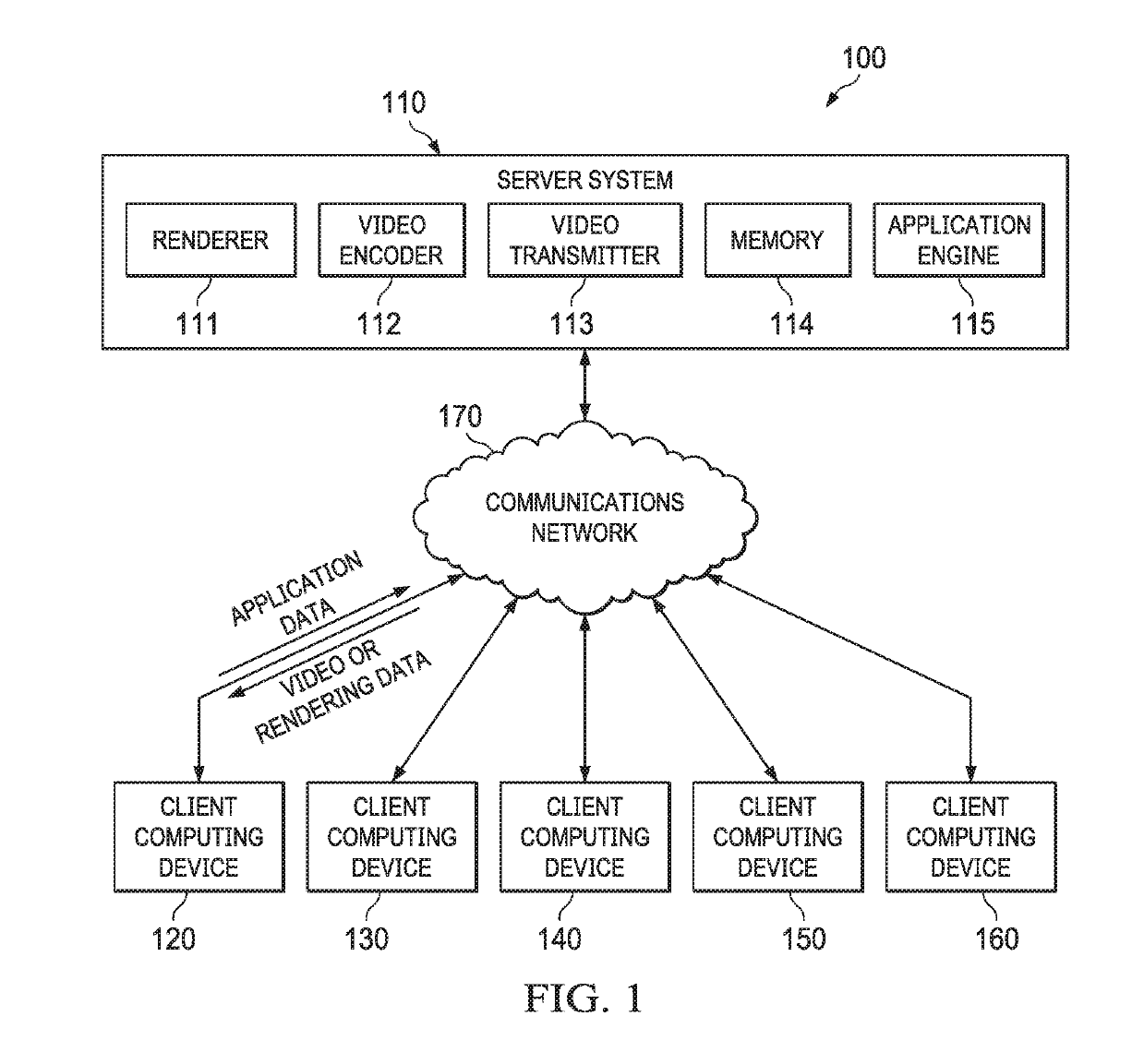
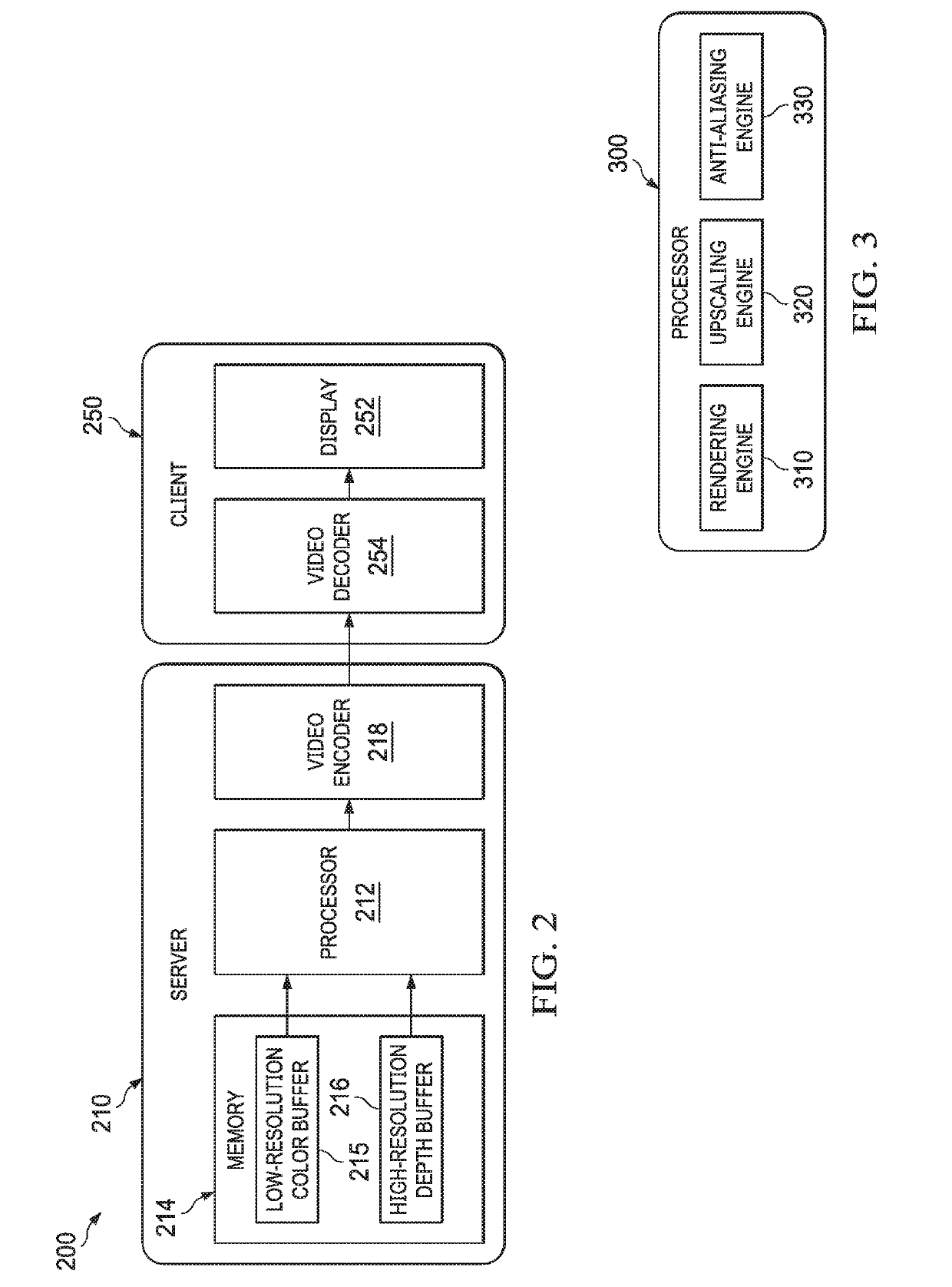
[0034]Rendering can be a resource intensive process that uses multiple passes to convert data into a format capable of being displayed on a display device. The rendering process can take into account various embodiments, variations, and scene parameters, such as determining if one object blocks another and to account for lighting and shading of a scene, to compute the color values for the pixels that will be displayed in each frame. The rendering process can be initially executed on a server system or set of server systems (server systems), such as a cloud-based renderer or a data center environment.

[0035]Real-time rendering can be used to render images or frames that are then encoded to form a video that can be delivered to client computing devices for display to one or more users. The video utilizes bandwidth and the amount of data in the video directly drives the time it takes to complete the transmission of the video to the client computing device.

[0036]Reducing the amount of co...


PUM


Abstract

The present disclosure is directed to a method to increase virtual machine density on a server system through adaptive rendering by dynamically determining when to shift video rendering tasks between the server system and a client computing device. In another embodiment, the adaptive rendering, using various parameters, can select one or more encoding and compression algorithms to use to prepare and process the video for transmission to the client computing device. In another embodiment, a video rendering system is disclosed that can adaptively alter how and where a video is rendered, encoded, and compressed.

Description

CROSS REFERENCE TO RELATED APPLICATION[0001]The present application is also related to U.S. patent application Ser. No. ______, filed May 1, 2018, entitled “HW-ASSISTED UPSCALING AND MULTI-SAMPLING USING A HIGH RESOLUTION DEPTH BUFFER” naming Rouslan Dimitrov, et. al, as inventors, having attorney docket number 17-SC-0065-US01, and incorporated herein by reference in its entirety.TECHNICAL FIELD[0002]This application is directed, in general, to a video upscaling and rendering process and, more specifically, to managing resources of a server system through the video rendering process.BACKGROUND[0003]In a cloud based application service, images can be rendered as part of an executing application, encoded into a video stream, and then delivered to a client computing device for display to a user. Certain applications can be more resource intensive than others. For example, a fast moving game application can require significantly more graphical processing to render images than a CAD appl...

Claims


Application Information

Patent Timeline
IPC IPC(8): H04N19/127H04N19/182H04N19/194
CPCH04N19/182H04L67/10H04N19/194H04N19/127H04N19/186H04N19/85H04N19/164H04N19/96H04N19/117H04L67/131G06F9/4856
Inventor DIMITROV, ROUSLANAMSINCK, CHRISVANDANOV, VIKTORDUTTA, SANTANUDONOVAN, WALTERLAPICQUE, OLIVIER
Owner NVIDIA CORP
Why Eureka
Try Eureka